Installation
Provides the complete installation procedures and connection examples required for the device.
Fixing the bracket and the product
General bracket
-
Determine the correct position to install the bracket using the provided drilling template.
 Info
Info- The optimal height for installing device is 136 cm.
-
Install the device where it does not reach the direct sunlight or UV light.
-
Adjust the installation position so that the face is not exposed to direct sunlight when a user tries to authenticate.
-
Secure the bracket tightly using the fixing screws at the location where the product will be mounted.
 Info
Info-
If installing the product on a concrete wall, drill a hole, insert a PVC anchor, and secure it with a fixing screw.
-
To avoid RF interference, a minimum separation distance must be maintained.
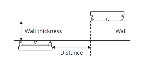
Wall thickness Distance 100 mm 200 mm 120 mm 180 mm 150 mm 150 mm 
- When using a mobile access card, install devices maintaining a minimum distance of 1 m between devices to avoid BLE interference.
-
-
After attaching the cable cover, tighten the six screws on the cover to secure it firmly.
 Info
InfoMake sure that the cable cover is completely closed after connecting it to the product to maintain the water-resistant and dust-resistant features (IP65 rating).
-
Mount the product on the fixed bracket.

-
Rotate the fixing screws to assemble the product with the bracket.
 Info
InfoWhen assembling the product with the bracket, you can use the included bracket fixing screw (Star Shaped) instead of the product fixing screw for enhanced security.
Tilting Bracket
Use the dedicated tilting bracket to adjust the authentication angle to suit the installation environment. The tilting bracket is sold separately.
-
Determine the correct position to install the bracket using the provided drilling template.
Info- The optimal height for installing device is 136 cm.
-
Install the device where it does not reach the direct sunlight or UV light.
-
Adjust the installation position so that the face is not exposed to direct sunlight when a user tries to authenticate.
-
Use the tilting bracket mounting screws to secure the back of the tilting bracket firmly to the installation location (wall).

Depending on the installation location, install the tilting bracket with the top and bottom orientation as follows.
-
When installing on the left side of the entrance: Install so the "R TOP" marking faces upward
-
When installing on the right side of the entrance: Install so the "L TOP" marking faces upward
 Info
Info-
If installing the product on a concrete wall, drill a hole, insert a PVC anchor, and secure it with a fixing screw.
-
To avoid RF interference, a minimum separation distance must be maintained.
Wall thickness Distance 100 mm 200 mm 120 mm 180 mm 150 mm 150 mm - When using a mobile access card, install devices maintaining a minimum distance of 1 m between devices to avoid BLE interference.
-
-
Join the front of the tilting bracket to the groove in the back, close it, and secure it with two screws in the upper and lower screw holes.
 Info
InfoIf you tighten the screws too much, the angle cannot be adjusted. Tighten the screws to the proper level.
-
After attaching the cable cover, tighten the six screws on the cover to secure it firmly.
InfoMake sure that the cable cover is completely closed after connecting it to the product to maintain the water-resistant and dust-resistant features (IP65 rating).
-
Secure the wall-mount bracket firmly on top of the tilting bracket.

-
Mount the product on the secured wall-mount bracket.

-
Tighten the product fixing screws to assemble the product and the wall-mount bracket.
 Info
InfoWhen assembling the product with the bracket, you can use the included bracket fixing screw (Star Shaped) instead of the product fixing screw for enhanced security.
-
Adjust the tilting bracket to the desired angle.

Power supply connection
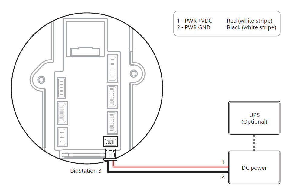
- DO NOT connect the device to the DC power supply (or adapter) and PoE power supply at the same time.
-
Use the IEC/EN 62368-1 approved power adapter that supports higher power consumption than the product. If you wish to connect and use another device to the power supply adapter, you should use an adapter with a current capacity which is the same or larger than the total power consumption required for the terminal and another device.
- Refer to the Power in the product specifications for maximum current consumption specifications.
- Use a separate power supply for Secure I/O 2, the electric lock, and the product respectively. If connecting and using the power supply to these devices together, the devices may malfunction.
-
When connecting the power supply, be aware of the distance between the device and the power supply. The device should be connected as close as possible to the power supply so that the length of the connecting cable is kept to a minimum. If cable connections are made improperly it may cause the device to malfunction. It is recommended to use a 16 AWG or 18 AWG cable if the product is far from the power supply. The connection distance may differ depending on the standard of the cable used and the installation environment. This product supports both DC 24 V and DC 12 V power, so check the maximum length according to the cable specification to ensure that the unit is properly powered.
Cable standard Max. extended length DC 12V DC 24V 16 AWG 50 m 150 m 18 AWG 30 m 136 m 20 AWG 20 m 90 m
- DO NOT extend the length of power cable when using the power adapter.
- DO NOT use the CAT5 UTP 2-Wire for power supply purpose.
Network Connection
TCP/IP
LAN connection (connecting to a hub)
You can connect to a hub using a standard CAT-5 or higher cable.
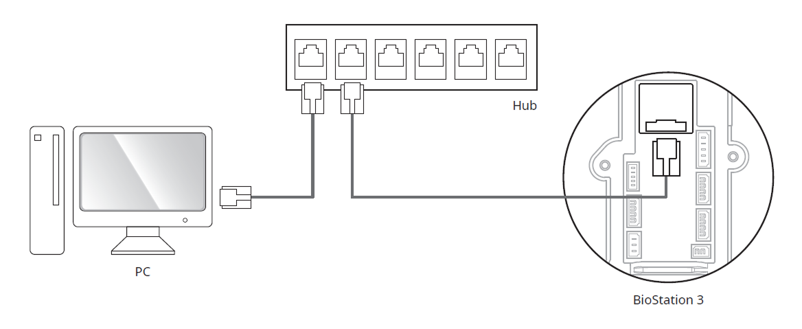
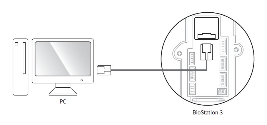
LAN connection (connecting to a PC directly)
This product supports automatic MDI/MDIX, so it can connect directly to a PC using either a crossover cable or a standard straight CAT-5 or higher cable.
When you use a gigabit network switch, see below information.
-
Use a CAT-5e UTP(Unshielded Twisted Pair) cable.
-
Use all 4 pairs (8 lines) of cable for network connection.
-
DO NOT use the pair of cable for other purpose.
Network ports and services
This device uses the following ports for network communication and stable service operation.
| Protocol | Service |
|---|---|
| TCP | Used for communication services between the server and the device, and for the device operation status switching service. |
| UDP | Used for the device discovery service to search for devices on the network. |
These ports are used to provide normal network features of the product. When configuring firewall rules or network security settings, allow the use of these ports.
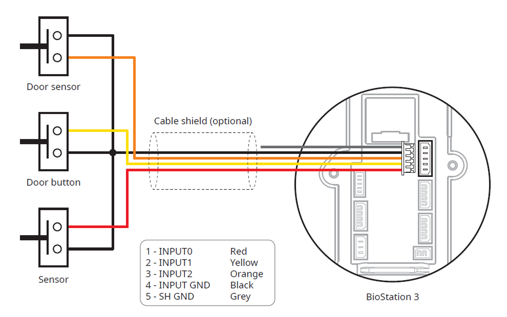
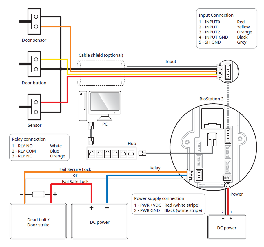
Input connection
Relay Connection
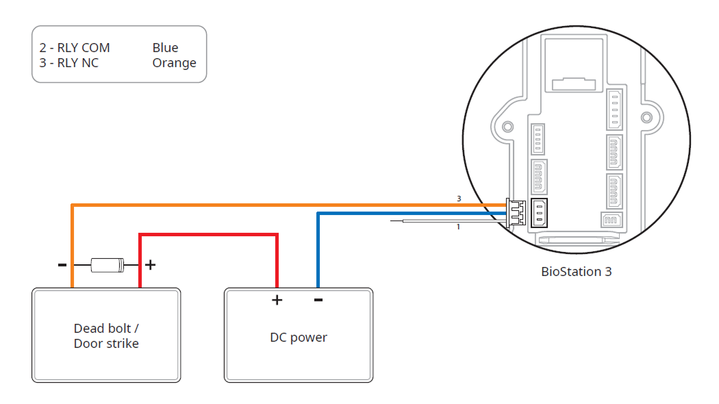
Fail Safe Lock
In order to use the Fail Safe Lock, connect N/C relay as shown in the figure below. There is normally a current flowing through the relay for the Fail Safe Lock. When the relay is activated, blocking the current flow, the door will open. If the power supply to the product is cut off due to a power failure or an external factor, the door will open.
-
Install a diode at both sides of the door lock wire as shown in the figure to protect the relay from the reverse current, which occurs when the door lock operates.
-
Use a separate power supply for the product and the door lock.
-
Suprema’s standalone intelligent readers contain internal relays that can directly lock/unlock doors without external controllers for added convenience. For access control applications in need of security, however, it is NOT recommended to use the internal relay of a reader to prevent any tampering attacks which can potentially trigger the door unlock. For such applications, it is highly recommended to use a separate relay unit for a lock control such as Suprema’s Secure I/O 2, DM-20 or CoreStation installed at a secure side of a door.
Take caution of the installation direction of the diode. Install the diode close to the door lock.
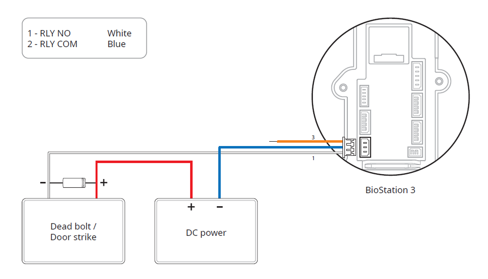
Fail Secure Lock
In order to use the Fail Secure Lock, connect N/O relay as shown in the figure below. There is normally no current flowing through the relay for the Fail Secure Lock. When the current flow is activated by the relay, the door will open. If the power supply to the product is cut off due to a power failure or an external factor, the door will lock.
-
Install a diode at both sides of the door lock wire as shown in the figure to protect the relay from the reverse current, which occurs when the door lock operates.
-
Use a separate power supply for the product and the door lock.
-
Suprema’s standalone intelligent readers contain internal relays that can directly lock/unlock doors without external controllers for added convenience. For access control applications in need of security, however, it is NOT recommended to use the internal relay of a reader to prevent any tampering attacks which can potentially trigger the door unlock. For such applications, it is highly recommended to use a separate relay unit for a lock control such as Suprema’s Secure I/O 2, DM-20 or CoreStation installed at a secure side of a door.
Take caution of the installation direction of the diode. Install the diode close to the door lock.
Automatic door connection
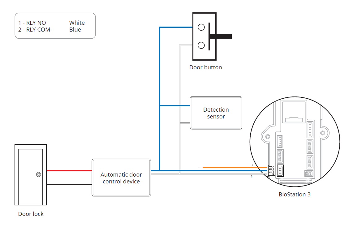
Connecting as a Standalone
The product can be connected to the door lock, door button, and door sensor directly without connecting a separate I/O device.
Suprema’s standalone intelligent readers contain internal relays that can directly lock/unlock doors without external controllers for added convenience. For access control applications in need of security, however, it is NOT recommended to use the internal relay of a reader to prevent any tampering attacks which can potentially trigger the door unlock. For such applications, it is highly recommended to use a separate relay unit for a lock control such as Suprema’s Secure I/O 2, DM-20 or CoreStation installed at a secure side of a door.
- The device can be used as a multi-door controller with the slave devices with the RS-485 cable. The slave devices are used as dummy readers and authentication is performed in the master device.
-
If a fingerprint authentication device is configured as a slave device in BioStation 3, you cannot add another BioStation 3 as a slave device.
-
If the fingerprint authentication device is the master device, BioStation 3 cannot be added as a slave device.
-
When you connect BioStation 3 as a slave device while BioStation 3 is the master device, only one BioStation 3 can be added as a slave device.
-
When BioStation 3 is the master device and another BioStation 3 is connected to it as a slave device, you can connect one additional Secure I/O 2 and DM-20 each.
-
When BioStation 3 is the master device and another BioStation 3 is connected to it as a slave device, you cannot connect additional OM-120.
- BioStation 3 cannot be used as a slave device when FaceStation F2 is the master device, and vice versa.
-
The maximum number of slave devices available to connect varies according to the authentication method, number of users, and number of devices. Also note that the number of slave devices affects the authentication performance.
-
Connect up to 31 slave devices to a master device. The bandwidth of RS-485 allows for up to 7 fingerprint authentication devices to be connected.
- For more information, contact the Suprema Technical Support Team.
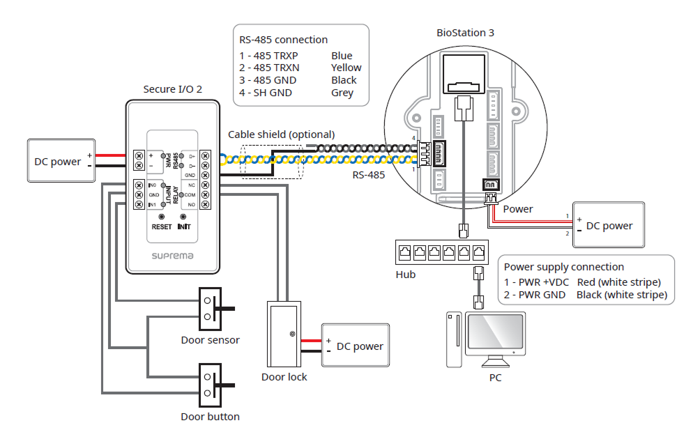
Connecting to Secure I/O 2
Secure I/O 2 is an I/O device, can be connected to the product with the RS-485 cable. Security can be maintained even if the connection between the product and Secure I/O 2 has been lost or the power supply to the product has been shut off due to external factors.
-
Use an AWG24 twisted pair with a maximum length of 1.2 km for the RS-485 cable.
-
It is recommended to use RS-485 cables with a characteristic impedance of 120 Ω.
-
If connecting with a RS-485 daisy chain, connect the termination resistor (120 Ω) to both ends of the daisy chain connection. If connected to the middle line, the signal level becomes smaller and the communication performance will deteriorate. Make sure to connect it to both ends of the daisy chain connection.
- The device can be used as a multi-door controller with the slave devices with the RS-485 cable. The slave devices are used as dummy readers and authentication is performed in the master device.
-
If a fingerprint authentication device is configured as a slave device in BioStation 3, you cannot add another BioStation 3 as a slave device.
-
If the fingerprint authentication device is the master device, BioStation 3 cannot be added as a slave device.
-
When you connect BioStation 3 as a slave device while BioStation 3 is the master device, only one BioStation 3 can be added as a slave device.
-
When BioStation 3 is the master device and another BioStation 3 is connected to it as a slave device, you can connect one additional Secure I/O 2 and DM-20 each.
-
When BioStation 3 is the master device and another BioStation 3 is connected to it as a slave device, you cannot connect additional OM-120.
- BioStation 3 cannot be used as a slave device when FaceStation F2 is the master device, and vice versa.
-
The maximum number of slave devices available to connect varies according to the authentication method, number of users, and number of devices. Also note that the number of slave devices affects the authentication performance.
-
Connect up to 31 slave devices to a master device. The bandwidth of RS-485 allows for up to 7 fingerprint authentication devices to be connected.
- For more information, contact the Suprema Technical Support Team.
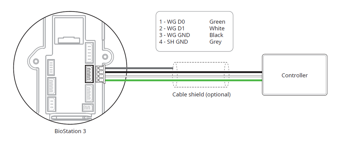
Wiegand Connection
Used as a Wiegand input device.
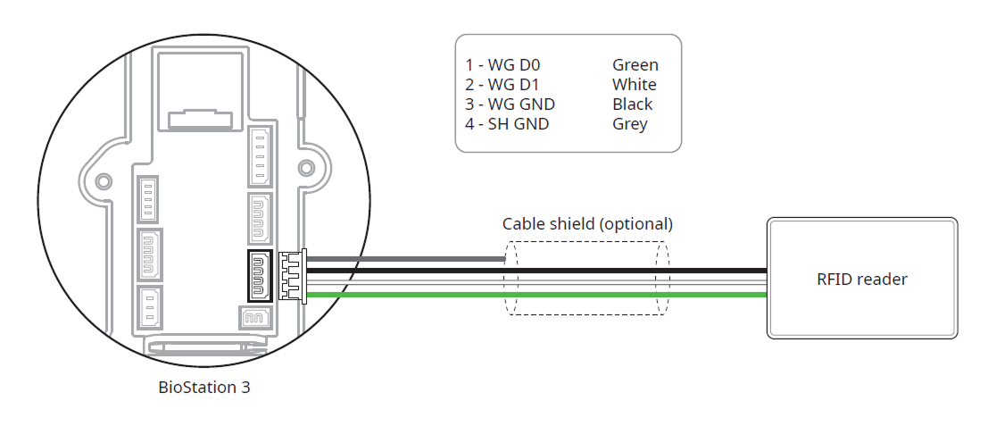
Used as a Wiegand output device.