Installation
Provides the complete installation procedures and connection examples required for the device.
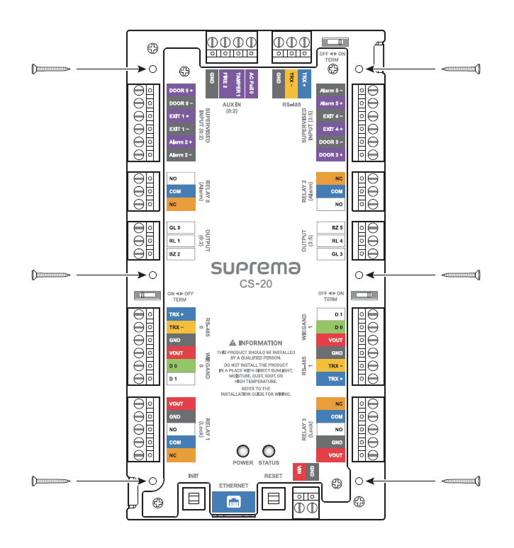
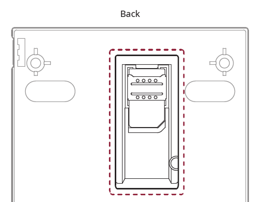
Product Fixation
Secure the product tightly with a fixing screw at the location to be mounted.
Power supply connection
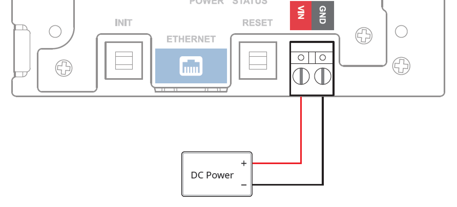
- Make sure to use separate power for the access control device and products.
-
Use the IEC/EN 62368-1 approved power adapter that supports higher power consumption than the product. If you wish to connect and use another device to the power supply adapter, you should use an adapter with a current capacity which is the same or larger than the total power consumption required for the terminal and another device.
- Refer to the Power in the product specifications for maximum current consumption specifications.
- DO NOT extend the length of power cable when using the power adapter.
It is recommended to connect and use an Uninterruptible Power Supply (UPS) to prevent power failure.
Power-specific reader and lock power specifications
| Power | Reader (maximum current, number of devices) | Lock (maximum current, number of devices) |
|---|---|---|
| DC 12V | 600mA (300mA x 2) | 1.2A (600mA x 2) |
| DC 24V | 300mA (150mA x 2) | 600mA (300mA x 2) |
| PoE+ (12V out) | 600mA (300mA x 2) | 600mA (600mA x 1) |
Maximum extension length by cable specification
The distance that can be connected may vary depending on the cable specifications and installation environment used for power connection. If cable connections are made improperly it may cause the device to malfunction. This product supports DC 12V, DC 24V, and PoE+ power, so ensure to correctly connect power by checking the maximum extension length according to each cable specification.
| Cable Specification | DC 12V | DC 24V | PoE+ (12V Output) | |||
|---|---|---|---|---|---|---|
| Reader (300mA) | Lock (600mA) | Reader (150mA) | Lock (300mA) | Reader (300mA) | Lock (600mA) | |
| 14 AWG | 380 m | 190 m | 1540 m | 770 m | 380 m | 190 m |
| 16 AWG | 240 m | 120 m | 960 m | 480 m | 240 m | 120 m |
| 18 AWG | 150 m | 75 m | 600 m | 300 m | 150 m | 75 m |
Network Connection
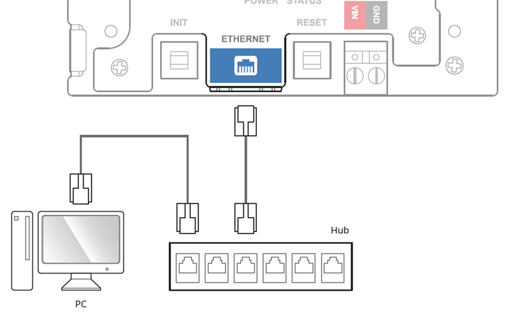
TCP/IP
LAN connection (connecting to a hub)
You can connect to a hub using a standard CAT-5 or higher cable.
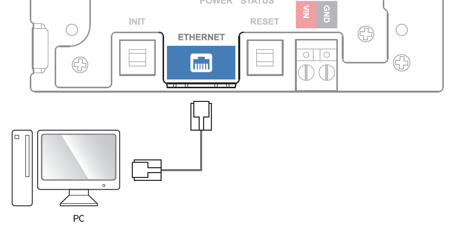
LAN connection (connecting to a PC directly)
This product supports automatic MDI/MDIX, so it can connect directly to a PC using a standard CAT-5e cable.
CS-20P Supports PoE+, which supplies power through an Ethernet cable. When using PoE+, only one Lock connection is supported.
Network ports and services
This device uses the following ports for network communication and stable service operation.
| Protocol | Service |
|---|---|
| TCP | Used for communication services between the server and the device, and for the device operation status switching service. |
| UDP | Used for the device discovery service to search for devices on the network. |
These ports are used to provide normal network features of the product. When configuring firewall rules or network security settings, allow the use of these ports.
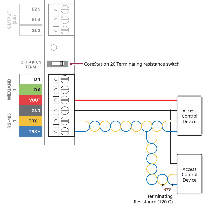
RS-485 Connection
This product supports three RS-485 ports, and by connecting the Door Interface in a daisy chain, up to 34 doors can be configured.
-
The total number of RS-485 devices connected to the product must not exceed 84. (Including Door Interface)
-
Up to 2 devices can be connected per port for RS-485 0 and RS-485 1.
-
If more than 3 devices are connected to a single RS-485 port, the desired device may not appear in the connectable list when searching for slave devices.
-
Use AWG26 or larger for RS-485 cables, and all wiring must comply with ANSI/NFPA 70 standards.
-
Use an AWG24 twisted pair with a maximum length of 1.2 km for the RS-485 cable.
-
It is recommended to use RS-485 cables with a characteristic impedance of 120 Ω.
-
Connect termination resistors (120 Ω) at both ends of the RS-485 daisy chain connection. If connected to the middle line, the signal level becomes smaller and the communication performance will deteriorate. Make sure to connect it to both ends of the daisy chain connection. Set this product's termination resistor switch to ON.
Relay Connection
The product has two types of relay ports—Alarm and Lock—each of which can be used for specific purposes.
-
Alarm: Can be connected to devices that generate warning sounds or intrusion alerts, such as warning lights, sirens, or buzzers.
-
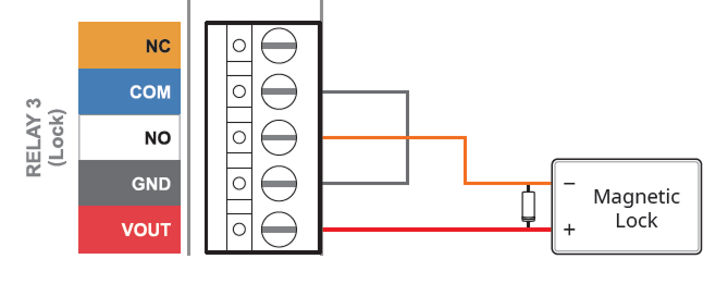
Lock: Can be connected to devices for door locking and unlocking, such as electric strike locks or magnetic locks.
When using a magnetic lock, connect the lock power directly.
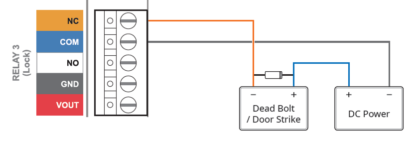
Fail Safe Lock
In order to use the Fail Safe Lock, connect the NC relay as shown in the figure below. There is normally a current flowing through the relay for the Fail Safe Lock. When the relay is activated, blocking the current flow, the door will open. If the power supply to the product is cut off due to a power failure or an external factor, the door will open.
Install a diode near both sides of the door lock wiring as shown in the figure to protect the relay from the reverse current that occurs when the door lock operates. Make sure to connect the Cathode (direction to the stripe) to the + part of the power while paying attention to the direction of the diode.
When using a magnetic lock, directly connect the lock power to the GND and VOUT of the Lock ports as shown in the figure below.
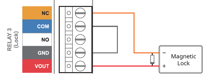
Only magnetic locks can be used when connecting the lock power directly.
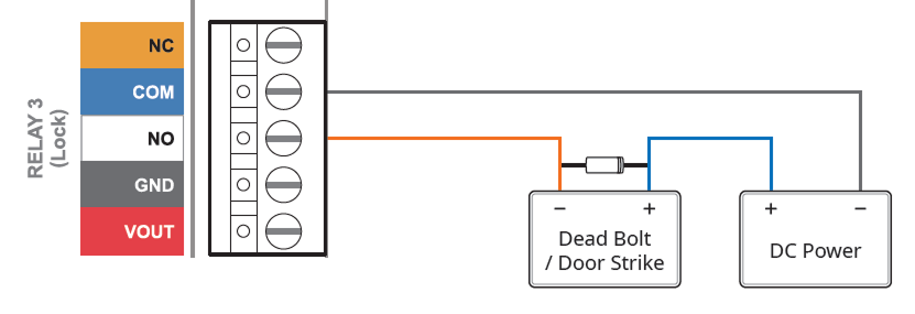
Fail Secure Lock
In order to use the Fail Secure Lock, connect NO relay as shown in the figure below. There is normally no current flowing through the relay for the Fail Secure Lock. When the current flow is activated by the relay, the door will open. If the power supply to the product is cut off due to a power failure or an external factor, the door will lock.
Install a diode near both sides of the door lock wiring as shown in the figure to protect the relay from the reverse current that occurs when the door lock operates. Make sure to connect the Cathode (direction to the stripe) to the + part of the power while paying attention to the direction of the diode.
When using a magnetic lock, directly connect the lock power to the GND and VOUT of the Lock ports as shown in the figure below.
Only magnetic locks can be used when connecting the lock power directly.
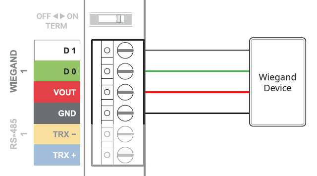
Wiegand Connection
Door sensor and exit button
SUPERVISED INPUT ports No. 0 - No. 5 can be set to be used for normal Input or Supervised Input.
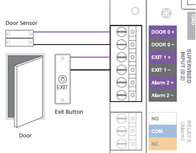
The SUPERVISED INPUT Alarm port can be used by connecting 1 kΩ, 2.2 kΩ, 4.7 kΩ, or 10 kΩ resistors. After connecting the appropriate resistor to the input device, set the resistor value the same in BioStar X.
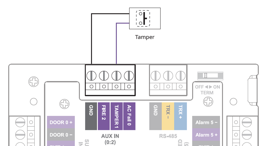
AUX IN
You can connect a power failure detector, tamper, or fire detector to the AUX IN port.
SAM card slot CS-20P
You can use a SAM (Secure Access Module) card.
CS-20P Use only slave devices directly connected to the CS-20P reader port when a SAM card is installed.
Factory default
You can factory reset the CoreStation in the Corestation Setup Manager.
-
Access the Corestation Setup Manager and click CONFIGURE.
-
Click Factory Default.
-
You can only use Factory Default when the root certificate is stored on the device.
-
You can view or manage the network settings of CoreStation and monitor the status of slave devices, input and output ports, and Wiegand ports by accessing the Corestation Setup Manager.
- CoreStation Setup Manager is supported on firmware version 1.0.0 or later.
-
For more information about the CoreStation Setup Manager, see the CoreStation Setup Manager.
-
The latest BioStar X version can be checked when the device is connected to the network and can be reset.
-
For more information, contact the Suprema Technical Support Team.