Getting Started
Provides initial procedures for getting started with the device.
Components
|
| |
| Quick Guide | ||
| ||
| CoreStation | Open Source Software Guide | |
|
|
|
| Fixing Screw x12 | Spacer x6 | Diode x4 |


- Components may vary according to the installation environment.
Accessory
This product can be purchased with the enclosure (ENCR-10) as an accessory.
The enclosure includes a power status LED board, power distribution board, power supply, and tamper. Refer to Enclosure Installation for how to install the product in the enclosure.
|
| ENCR-10 |

- The ENCR-10 is designed to be mounted on a wall for use. Install it at a safe and convenient height without restrictions on installation height.
-
The ENCR-10 components include screws for housing fixation, screws for product fixation, and screws for power device connection. Use each screw correctly according to its purpose.
-
Fixing screws for the enclosure (diameter: 4 mm, length: 25 mm) x4
-
Fixing screws for the device (diameter: 3 mm, length: 5 mm) x6
-
Fixing screws for the power supply cable (diameter: 3 mm, length: 8 mm) x1
-
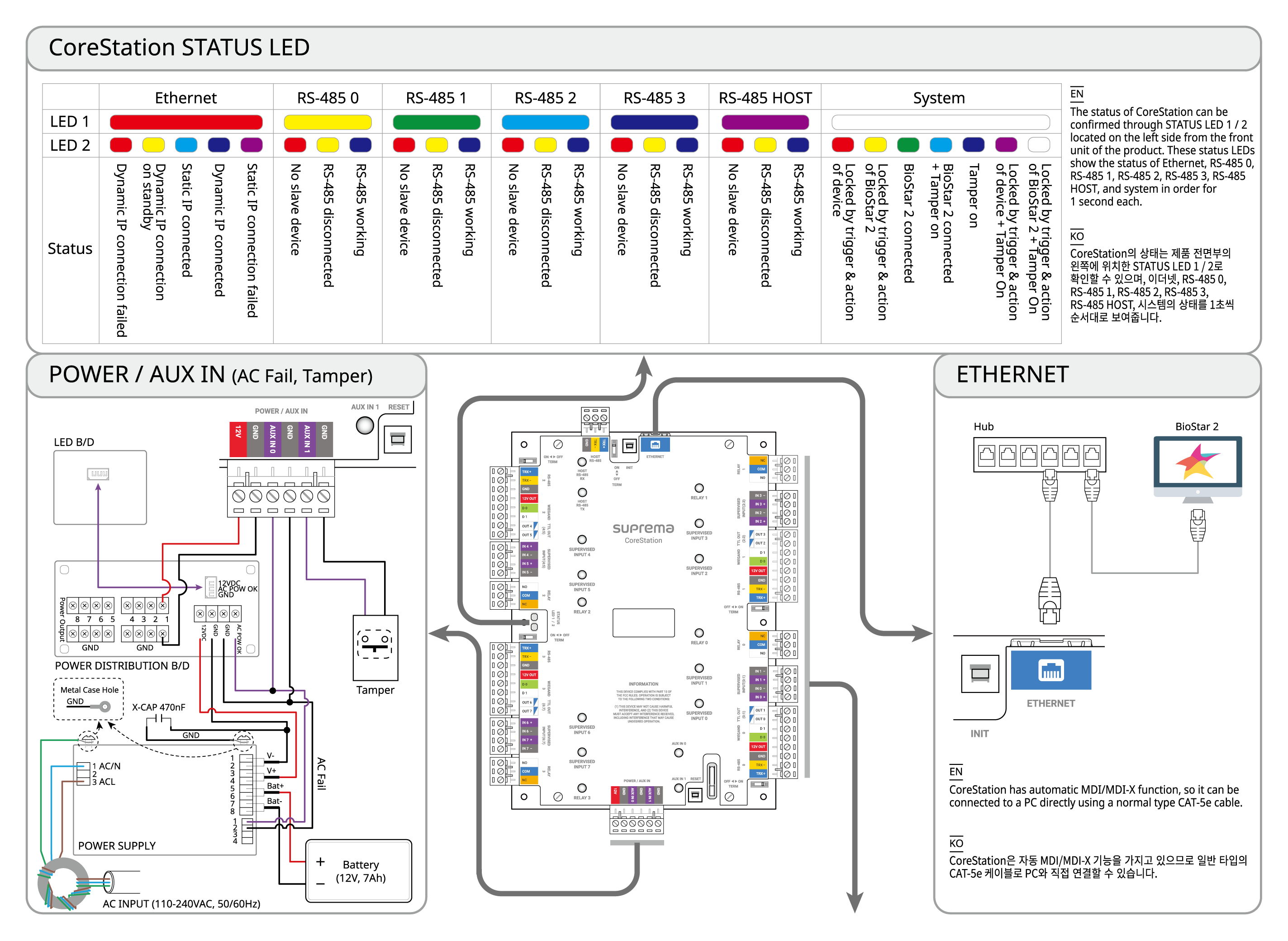
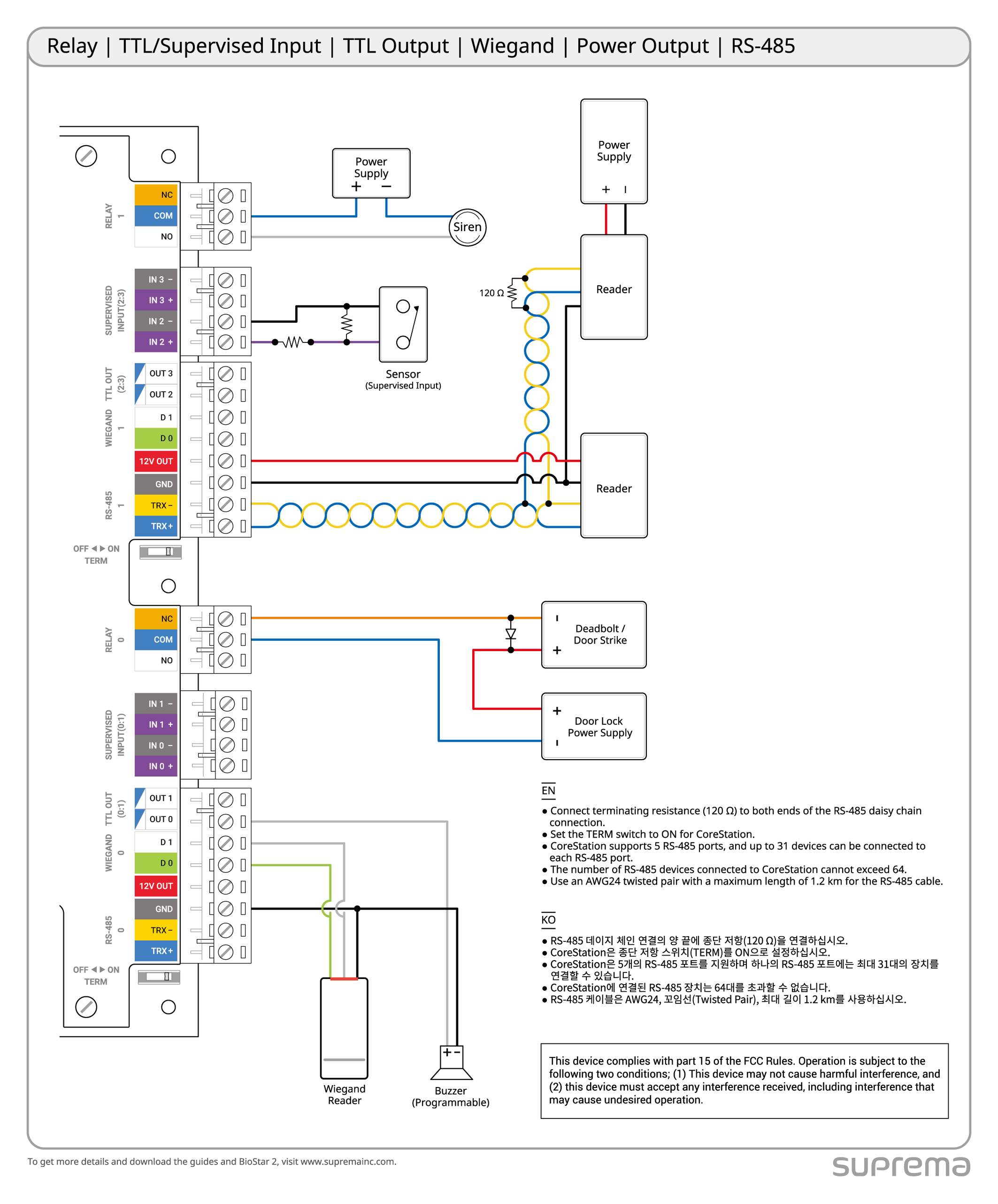
Name and function of each part

| No. | Name | No. | Name |
|---|---|---|---|
| 1 | HOST RS-485 connection | 20 | RESET button |
| 2 | HOST RS-485 termination resistor switch | 21 | AUX IN (0, 1) connection |
| 3 | INIT button | 22 | CoreStation power connection (DC 12V IN) |
| 4 | ETHERNET connection | 23 | RELAY 3 connection |
| 5 | RELAY 1 connection | 24 | SUPERVISED INPUT (6:7) or Input (6:7) connection |
| 6 | SUPERVISED INPUT (2:3) or Input (2:3) connection | 25 | OUTPUT (6:7) connection |
| 7 | OUTPUT (2:3) connection | 26 | WIEGAND 3 connection |
| 8 | WIEGAND 1 connection | 27 | 12VDC output |
| 9 | 12VDC output | 28 | RS-485 3 connection |
| 10 | RS-485 1 connection | 29 | RS-485 3 termination resistor switch |
| 11 | RS-485 1 termination resistor switch | 30 | CoreStation status LED |
| 12 | RELAY 0 connection | 31 | RELAY 2 connection |
| 13 | SUPERVISED INPUT (0:1) or Input (0:1) connection | 32 | SUPERVISED INPUT (4:5) or Input (4:5) connection |
| 14 | OUTPUT (0:1) connection | 33 | OUTPUT (4:5) connection |
| 15 | WIEGAND 0 connection | 34 | WIEGAND 2 connection |
| 16 | 12VDC output | 35 | 12VDC output |
| 17 | RS-485 0 connection | 36 | RS-485 2 connection |
| 18 | RS-485 0 termination resistor switch | 37 | RS-485 2 termination resistor switch |
| 19 | RTC battery |
-
Press the INIT button for more than 2 seconds after initializing the product linked to the device to connect it to another device.
-
Press the RESET button to reboot the product.
-
You can use the product’s power output (12V, up to 1.5A) to power the Wiegand device when connecting it to the product. If you connect three Wiegand devices that consume 200mA, you can connect devices that consume up to 900mA to the remaining power output terminals.
-
The RTC battery capacity is 226mAh, and the expected lifespan may vary depending on the installation environment and usage method. When replacing the RTC battery, please adhere to CR2032.
Communication status LED
| LED | Status |
|---|---|
| HOST RS-485 TX | Orange blinking: Transmitting RS-485 data |
| HOST RS-485 RX | Green blinking: Receiving RS-485 data |
| RELAY (0 ~ 3) | Red lit: Relay operation |
| SUPERVISED INPUT (0 ~ 7) | When using input - Green lit: Normal close - Off: Normal open |
| When using supervised input - Green lit: Normal close (short circuit), Normal open, switch on - Off: Switch off | |
| AUX IN (0, 1) | Orange lit: Receiving AUX signal |
Access control level
| Feature | Level |
|---|---|
| Destructive Attack | I |
| Line Security | I |
| Endurance | IV |
| Standby Power | I |
| Single Point Locking Device with Key Locks | I |
CoreStation status LED
The product's status can be checked with STATUS LED 1 / 2 located on the left side of the product's front, which sequentially displays the status of Ethernet, RS-485 0, RS-485 1, RS-485 2, RS-485 3, RS-485 HOST, and the system in intervals of one second.
| Item | LED 1 | LED 2 | Status |
|---|---|---|---|
| Ethernet | Red | Red | Dynamic IP connection failed |
| Red | Yellow | Waiting for dynamic IP connection | |
| Red | Sky blue | Static IP connection successful | |
| Red | Blue | Dynamic IP connection successful | |
| Red | Magenta | Static IP connection failed | |
| Red | Off | HW error | |
| RS-485 0 | Yellow | Red | No slave device |
| Yellow | Yellow | Slave device disconnected | |
| Yellow | Blue | Slave device normal | |
| Yellow | Off | HW error | |
| RS-485 1 | Green | Red | No slave device |
| Green | Yellow | Slave device disconnected | |
| Green | Blue | Slave device normal | |
| Green | Off | HW error | |
| RS-485 2 | Sky blue | Red | No slave device |
| Sky blue | Yellow | Slave device disconnected | |
| Sky blue | Blue | Slave device normal | |
| Sky blue | Off | HW error | |
| RS-485 3 | Blue | Red | No slave device |
| Blue | Yellow | Slave device disconnected | |
| Blue | Blue | Slave device normal | |
| Blue | Off | HW error | |
| RS-485 HOST | Magenta | Red | No slave device |
| Magenta | Yellow | Slave device disconnected | |
| Magenta | Blue | Slave device normal | |
| Magenta | Off | HW error | |
| System | White | Red | System lock (Device's operational conditions and behavior) |
| White | Yellow | System lock (BioStar X's operational conditions and behavior) | |
| White | Green | BioStar X connection successful | |
| White | Sky blue | BioStar X connection successful + Tamper on | |
| White | Blue | Tamper on | |
| White | Magenta | System lock (Device's operational conditions and behavior) + Tamper on | |
| White | White | System lock (BioStar X's operational conditions and behavior) + Tamper on | |
| Magenta | Magenta | Database migration in progress |
Installation example
This product is a centralized access control system capable of performing biometric authentication. Designed for enterprise-grade systems, the product can store information for up to 500,000 users and perform 400,000 fingerprint matches per second.
Integrates with BioStar X to enable both access control and time and attendance, and provides various interfaces, including RS-485 (OSDP), Wiegand, supervised input, and AUX.
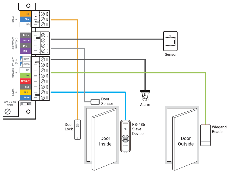
System diagram
Connect up to 64 RS-485 devices, and daisy-chain a Door Module to support up to 132 Wiegand devices.

Overall connection diagram
For reliable product usage, it is recommended to use a dedicated housing. The housing includes an LED control board, power control board, power device, battery, and tamper.
Do not connect to a socket controlled by a switch A.