Getting Started
Provides initial procedures for getting started with the device.
Components
|
|
| Quick Guide | |
| |
| Door Interface | Open Source Software Guide |
|
|
| Fixing Screw x6 | Diode x4 |


- Components may vary according to the installation environment.
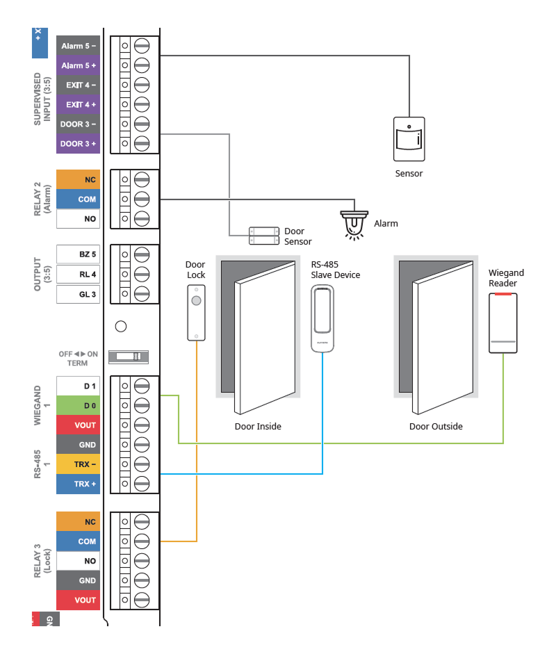
Name and function of each part

| No. | Name |
|---|---|
| 1 | AUX IN (0:2) connection |
| 2 | RS-485 connection |
| 3 | RS-485 termination resistor switch |
| 4 | SUPERVISED INPUT (3:5) or Input (3:5) connection |
| 5 | RELAY 2 (Alarm) connection |
| 6 | OUTPUT (3:5) connection |
| 7 | RS-485 1 termination resistor switch |
| 8 | WIEGAND 1 connection |
| 9 | RS-485 1 connection |
| 10 | RELAY 3 (Lock) connection |
| 11 | Power connection for Door Interface (DC 12V / DC 24V IN) |
| 12 | RESET button |
| 13 | INIT button |
| 14 | RELAY 1 (Lock) connection |
| 15 | WIEGAND 0 connection |
| 16 | RS-485 0 connection |
| 17 | RS-485 0 termination resistor switch |
| 18 | OUTPUT (0:2) connection |
| 19 | RELAY 0 (Alarm) connection |
| 20 | SUPERVISED INPUT (0:2) or Input (0:2) connection |
-
Press the INIT button for more than 2 seconds after initializing the product linked to the device to connect it to another device.
-
Press the RESET button to reboot the product.
-
You can use the product's reader power output (12 Vdc, up to 0.6 A / 24 Vdc, up to 0.3 A) as power for the reader when connecting the product to the reader. You can connect two readers consuming 0.3 A based on 12 Vdc power output.
Door Interface status LED
The product's status can be checked at the STATUS located on the right side of the front of the product, displaying the status of Ethernet, RS-485, RS-485 0, RS-485 1, in order every second.
| Item | LED | Status |
|---|---|---|
| RS-485 | Magenta/blue blinking | Master device normal |
| Magenta/yellow blinking | Master device disconnected | |
| RS-485 0 | Yellow/blue blinking | Slave device normal |
| Yellow/yellow blinking | Slave device disconnected | |
| Yellow/red blinking | No slave device | |
| RS-485 1 | Green/blue blinking | Slave device normal |
| Green/yellow blinking | Slave device disconnected | |
| Green/red blinking | No slave device | |
| System | White/white blinking | System lock (BioStar X's operational conditions and behavior) + Tamper on |
| White/magenta blinking | System lock (Device's operational conditions and behavior) + Tamper on | |
| White/blue blinking | Tamper on | |
| White/cyan blinking | BioStar X connection successful + Tamper on | |
| White/green blinking | BioStar X connection successful | |
| White/yellow blinking | System lock (BioStar X's operational conditions and behavior) | |
| White/red blinking | System lock (Device's operational conditions and behavior) |
Installation example
This product can easily configure up to 2 access doors as an extension module.
Integrates with BioStar X to enable both access control and time and attendance, and provides various interfaces, including RS-485 (OSDP), Wiegand, supervised input, and AUX.
System diagram
This product supports 3 RS-485 ports, and by daisy-chaining multiple Door Interfaces to the master device, you can configure up to 34 doors.
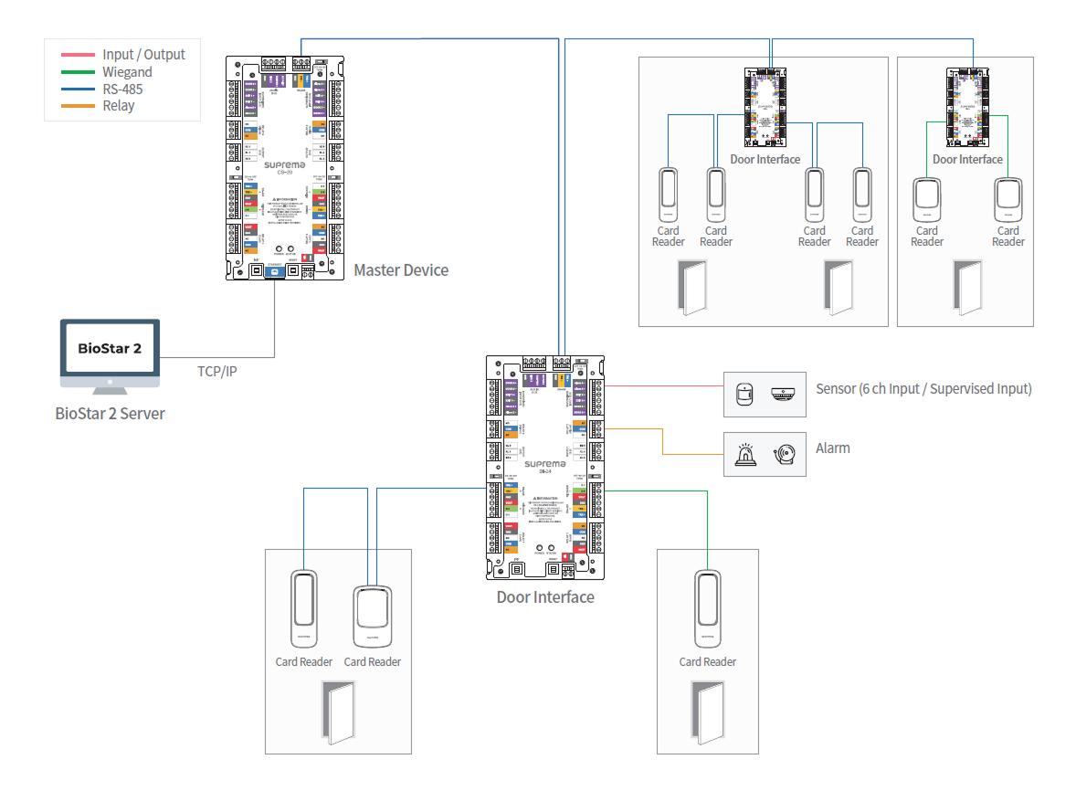
-
Up to 2 devices can be connected per port for RS-485 0 and RS-485 1.
-
If more than 3 devices are connected to a single RS-485 port, the desired device may not appear in the connectable list when searching for slave devices.
-
When connecting the Door Interface as a slave to the host port of the master device, you can open access doors by identifying the facility code of the card through the Facility Code for Offline Mode, even if the connection with the master device is lost for the slave devices connected to the Door Interface.
Overall connection diagram
