Installation
Provides the complete installation procedures and connection examples required for the device.
Use bracket
-
Secure the bracket tightly using the fixing screws at the location where the product will be mounted.
InfoIf installing the product on a concrete wall, drill a hole, insert a PVC anchor, and secure it with a fixing screw.
-
Mount the product on the fixed bracket.

Use spacer
Secure the product tightly using spacers and fixing screws at the position where the product will be mounted.
![]()
If installing the product on a concrete wall, drill a hole, insert a PVC anchor, and secure it with a fixing screw.
Power supply connection
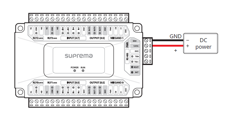
- Make sure to use separate power for the access control device and products.
-
Use the IEC/EN 62368-1 approved power adapter that supports higher power consumption than the product. If you wish to connect and use another device to the power supply adapter, you should use an adapter with a current capacity which is the same or larger than the total power consumption required for the terminal and another device.
- Refer to the Power in the product specifications for maximum current consumption specifications.
- Use a separate power supply for Secure I/O 2, the electric lock, and the product respectively. If connecting and using the power supply to these devices together, the devices may malfunction.
- DO NOT extend the length of power cable when using the power adapter.
RS-485 Connection
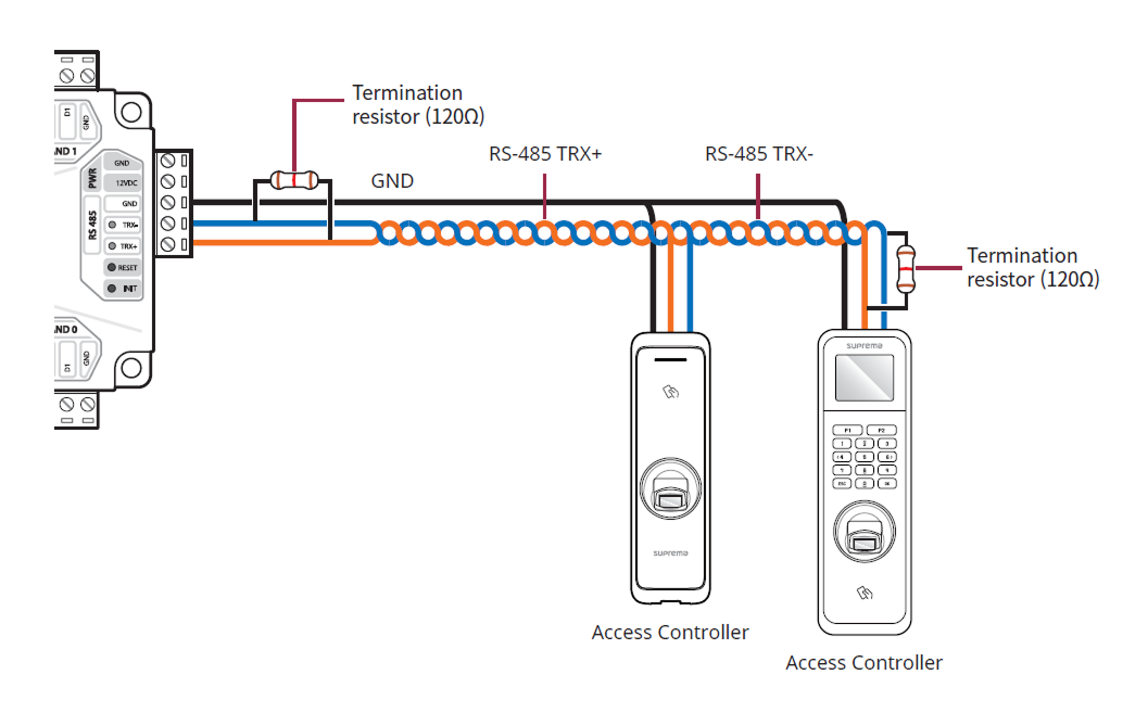
-
Use an AWG24 twisted pair with a maximum length of 1.2 km for the RS-485 cable.
-
It is recommended to use RS-485 cables with a characteristic impedance of 120 Ω.
-
If connecting with a RS-485 daisy chain, connect the termination resistor (120 Ω) to both ends of the daisy chain connection. If connected to the middle line, the signal level becomes smaller and the communication performance will deteriorate. Make sure to connect it to both ends of the daisy chain connection.
-
You can connect up to 31 card readers with the product, and up to 7 biometric devices can be connected in combination with 24 card readers.
-
If XPass or XPass 2 is connected to the master device, only card authentication can be used.
Relay Connection
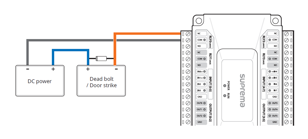
Fail Safe Lock
In order to use the Fail Safe Lock, connect the NC relay as shown in the figure below. There is normally a current flowing through the relay for the Fail Safe Lock. When the relay is activated, blocking the current flow, the door will open. If the power supply to the product is cut off due to a power failure or an external factor, the door will open.
Connect a diode to both ends of the power input as shown in the figure below when installing a deadbolt or a door strike. Make sure to connect the Cathode (direction to the stripe) to the + part of the power while paying attention to the direction of the diode.
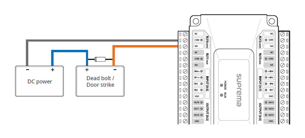
Fail Secure Lock
In order to use the Fail Secure Lock, connect NO relay as shown in the figure below. There is normally no current flowing through the relay for the Fail Secure Lock. When the current flow is activated by the relay, the door will open. If the power supply to the product is cut off due to a power failure or an external factor, the door will lock.
Connect a diode to both ends of the power input as shown in the figure below when installing a deadbolt or a door strike. Make sure to connect the Cathode (direction to the stripe) to the + part of the power while paying attention to the direction of the diode.
Wiegand Connection
Connect the product to a 12 V, 3.1 A power supply when connecting a Wiegand device.
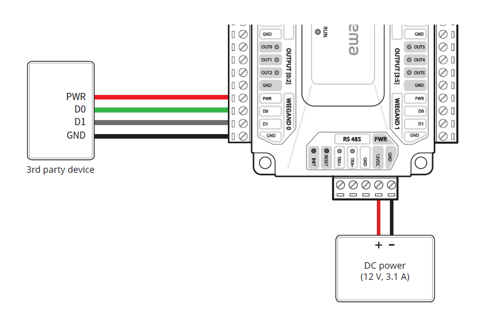
You can use a 12 V, up to 1.5 A power supply when connecting a Wiegand device to the product. When connecting a device requiring 1.0 A to WIEGAND 0, only 500 mA can be used on WIEGAND 1.
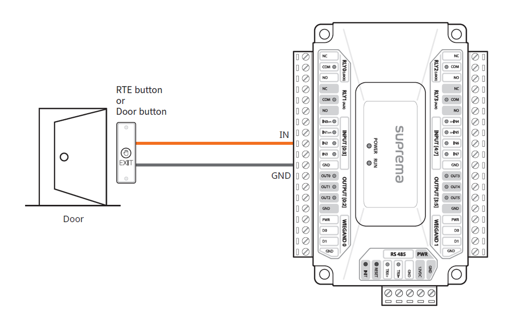
Exit button
The IN0(SP), IN1(SP), IN4(SP), IN5(SP) ports support the Supervised Input feature and operate only as N/C. To avoid using Supervised Input, connect to the IN2, IN3, IN6, IN7 ports.
Door sensor
The IN0(SP), IN1(SP), IN4(SP), IN5(SP) ports support the Supervised Input feature and operate only as N/C. To avoid using Supervised Input, connect to the IN2, IN3, IN6, IN7 ports.