Getting Started
Provides initial procedures for getting started with the device.
Caution
Connection of the expansion module is not supported on standard firmware, so a separate custom firmware is required.
Components
|
|
|
| Expansion Module | Pin Map Label | Fixing Screws x2 |


|
|
| RS-232C Cable | RS-485 Cable |
|
|
| USB Expansion Port Connection Cable (BioStation 3) | USB Expansion Port Connection Cable (BioStation 2a) |

Info
- Components may vary according to the installation environment.
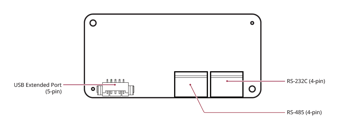
Name and function of each part
-
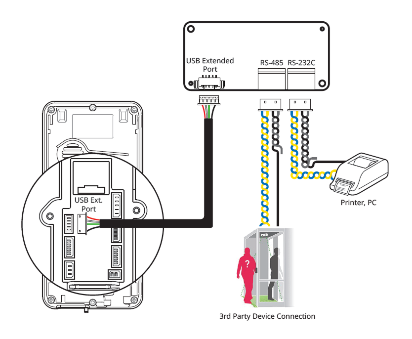
USB Expansion Port (5-pin): Connects the device to the expansion module.
-
RS-485 (4-pin): Connect the RS-485 cable.
-
RS-232C (4-pin): Connect the RS-232C cable.
Cables and connectors
RS-232C

| Pin | Name | Color |
|---|---|---|
| 1 | 232 TX | Blue |
| 2 | 232 RX | Yellow |
| 3 | 232 GND | Black |
| 4 | SH GND | Gray |
RS-485
| Pin | Name | Color |
|---|---|---|
| 1 | 485 TRXP | Blue |
| 2 | 485 TRXN | Yellow |
| 3 | 485 GND | Black |
| 4 | SH GND | Gray |
USB Expansion Port Connection Cable

| Pin | Name | Color |
|---|---|---|
| 1 | MAIN VBUS | Red |
| 2 | MAIN DM | White |
| 3 | MAIN DP | Green |
| 4 | NC | - |
| 5 | MAIN GND | Black |
Installation example
Caution
Connection of the expansion module is not supported on standard firmware, so a separate custom firmware is required.
By equipping the Suprema device with an expansion module, you can additionally use RS-485 and RS-232C ports.
The Suprema devices that can accommodate the expansion module are as follows.