Getting Started
Provides initial procedures for getting started with the device.
Components
|
|
| Input Module | Drilling Template |


|
|
|
|
|
| Fixing Screw x12 | Spacer x6 | Diode x2 | Quick Guide | Open Source Software Guide |


- Components may vary according to the installation environment.
Accessory
This product can be purchased with the enclosure (ENCR-10) as an accessory, and you can install two products in one enclosure.
The enclosure includes a power status LED board, power distribution board, power supply, and tamper. Refer to Enclosure Installation for how to install the product in the enclosure.
|
| ENCR-10 |

- The ENCR-10 is designed to be mounted on a wall for use. Install it at a safe and convenient height without restrictions on installation height.
-
The ENCR-10 components include screws for housing fixation, screws for product fixation, and screws for power device connection. Use each screw correctly according to its purpose.
-
Fixing screws for the enclosure (diameter: 4 mm, length: 25 mm) x4
-
Fixing screws for the device (diameter: 3 mm, length: 5 mm) x6
-
Fixing screws for the power supply cable (diameter: 3 mm, length: 8 mm) x1
-
Name and function of each part

| No. | Name |
|---|---|
| 1 | RESET button |
| 2 | INIT button |
| 3 | SUPERVISED INPUT (9:11) connection |
| 4 | SUPERVISED INPUT (6:8) connection |
| 5 | RELAY 1 connection |
| 6 | TAMPER or AUX IN (0:1) connection |
| 7 | RS-485 termination resistor switch |
| 8 | RS-485 connection |
| 9 | POWER connection (DC 12 or 24 V) |
| 10 | RELAY 0 connection |
| 11 | SUPERVISED INPUT (3:5) connection |
| 12 | SUPERVISED INPUT (0:2) connection |
-
Press the INIT button for more than 2 seconds after initializing the product linked to the device to connect it to another device.
-
Press the RESET button to reboot the product.
LED Status Indicator
You can check the product operating status by the color of the LED status indicator.
| Item | LED | Status |
|---|---|---|
| POWER | Red Lit | Power On |
| STATUS | Green Lit | Connected status via secure session |
| Blue Lit | Not connected to the master device | |
| Pink Lit | In the process of upgrading firmware | |
| Yellow Lit | Communication error due to different key or packet loss in OSDP causing RS-485 | |
| Sky Blue Lit | Connected status without secure session | |
| Green blinking | Final input waiting status during configuration initialization | |
| Green Lit | Configuration initialization completed | |
| SUPERVISED INPUT (0~11) | Red Lit | Receiving input signal status |
| RELAY (0, 1) | Red Lit | Relay Operation |
| RS-485 TX | Orange blinking | In the process of transmitting RS-485 data |
| RS-485 RX | Green blinking | In the process of receiving RS-485 data |
| AUX IN (0, 1) | Orange Lit | In the process of receiving AUX signal |
| TAMPER | Orange Lit | Tamper action |
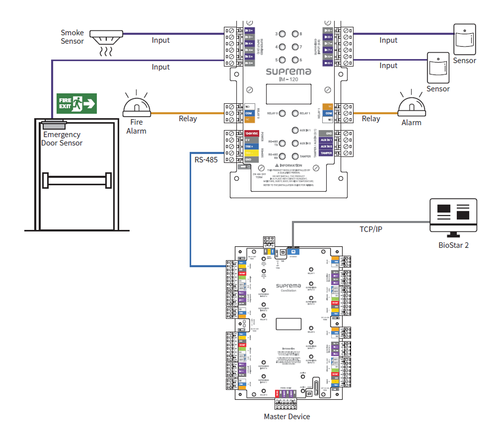
Installation example
This product supports immediate relay actions for input detected in real-time in conjunction with BioStar X, and can also perform relay actions or log data for inputs detected when disconnected from the master device.
Supports 1-channel RS-485 for network with the master device, 12 channels of Supervised Input for detecting short circuits, on, off states, and 2-channel relay, 2-channel AUX input, and 1-channel tamper input.