Installation
Provides the complete installation procedures and connection examples required for the device.
Product Fixation
-
Secure the spacer with fixing screws at the location where the product will be mounted.
-
Tighten the product onto the secured spacer using fixing screws.

Power supply connection
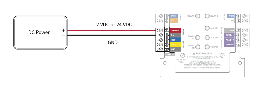
- Make sure to use separate power for the access control device and products.
-
Use the IEC/EN 62368-1 approved power adapter that supports higher power consumption than the product. If you wish to connect and use another device to the power supply adapter, you should use an adapter with a current capacity which is the same or larger than the total power consumption required for the terminal and another device.
- Refer to the Power in the product specifications for maximum current consumption specifications.
- DO NOT extend the length of power cable when using the power adapter.
It is recommended to connect and use an Uninterruptible Power Supply (UPS) to prevent power failure.
RS-485 Connection
You can connect the product to the master device.
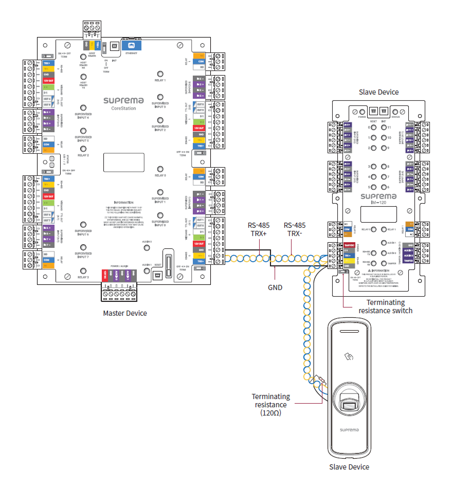
-
Use AWG26 or larger for RS-485 cables, and all wiring must comply with ANSI/NFPA 70 standards.
-
Use an AWG24 twisted pair with a maximum length of 1.2 km for the RS-485 cable.
-
It is recommended to use RS-485 cables with a characteristic impedance of 120 Ω.
-
Connect termination resistors (120 Ω) at both ends of the RS-485 daisy chain connection. If connected to the middle line, the signal level becomes smaller and the communication performance will deteriorate. Make sure to connect it to both ends of the daisy chain connection. Set this product's termination resistor switch to ON.
Relay Connection
You can control the entrance door locking mechanism or alarm system with the relay of this product. Refer to the guide of the device to be connected and connect the relay as NC or NO.
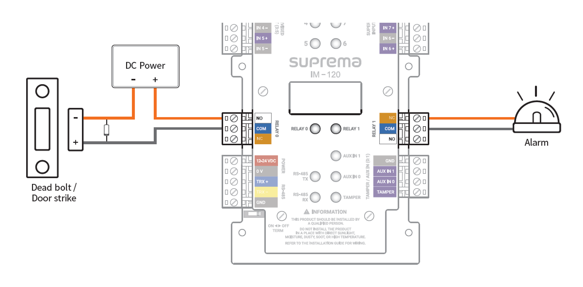
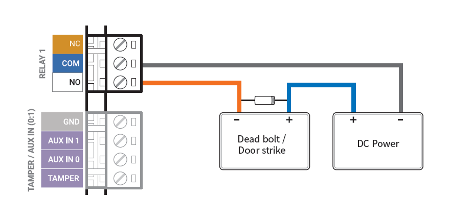
Fail Safe Lock
In order to use the Fail Safe Lock, connect the NC relay as shown in the figure below. There is normally a current flowing through the relay for the Fail Safe Lock. When the relay is activated, blocking the current flow, the door will open. If the power supply to the product is cut off due to a power failure or an external factor, the door will open.
Connect a diode to both ends of the power input as shown in the figure below when installing a deadbolt or a door strike. Make sure to connect the Cathode (direction to the stripe) to the + part of the power while paying attention to the direction of the diode.
Do not connect the relay of this product in duplicate to the device connected to the relay port of the master device.
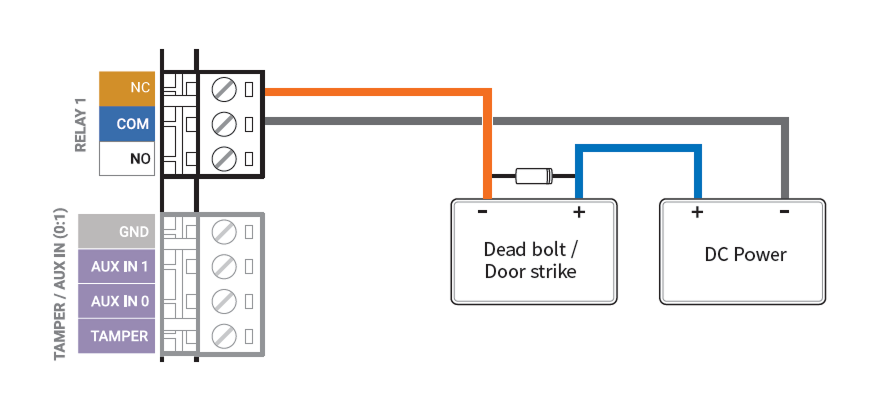
Fail Secure Lock
In order to use the Fail Secure Lock, connect NO relay as shown in the figure below. There is normally no current flowing through the relay for the Fail Secure Lock. When the current flow is activated by the relay, the door will open. If the power supply to the product is cut off due to a power failure or an external factor, the door will lock.
Connect a diode to both ends of the power input as shown in the figure below when installing a deadbolt or a door strike. Make sure to connect the Cathode (direction to the stripe) to the + part of the power while paying attention to the direction of the diode.
Do not connect the relay of this product in duplicate to the device connected to the relay port of the master device.
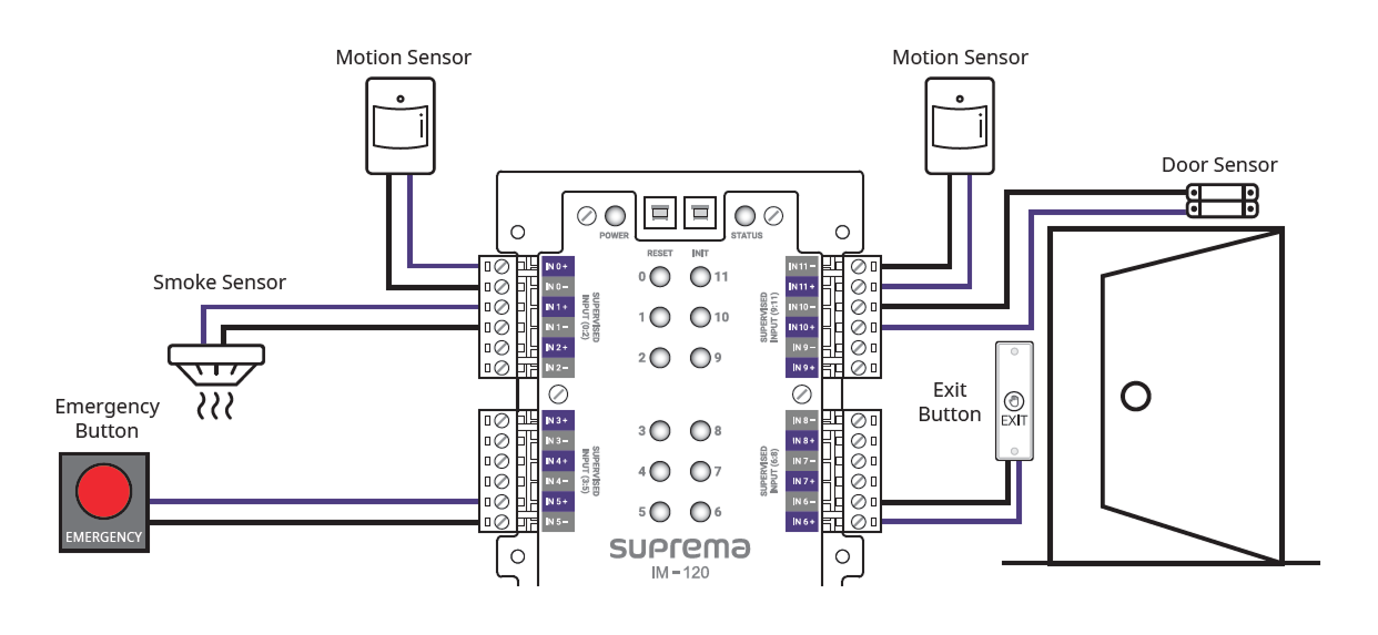
Supervised Input Connection
You can connect fire detection sensors, heat detection sensors, burglar sensors, door sensors, exit buttons, etc. SUPERVISED INPUT Terminals 0~11 can detect voltage flowing through the circuit to monitor the device's short circuit, open circuit, on, and off states, and can also be used as general input.
Set the actions based on the product's status in BioStar X and monitor the input status.
-
Do not connect the product's inputs in duplicate to the devices connected to the master device's input ports.
-
This product can connect resistors of 1kΩ, 2.2kΩ, 4.7kΩ, and 10kΩ. After connecting the appropriate resistor to the input device, set the resistor value the same in BioStar X.
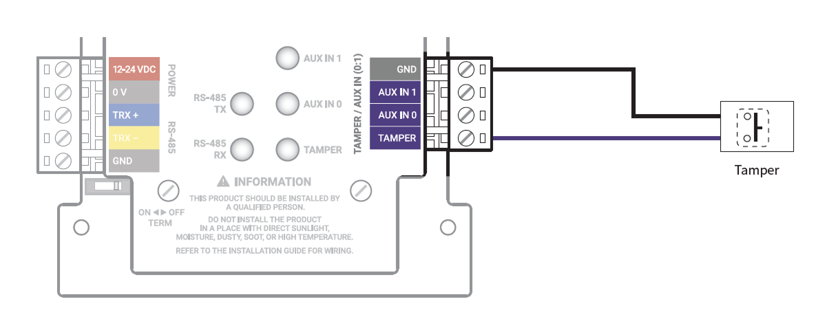
Tamper Connection
It can trigger an alarm or leave an event log if the product is detached from its installation due to external factors.
Enclosure installation
For physical and electrical protection, the product can be installed inside the enclosure (ENCR-10). The enclosure includes a power status LED board, power distribution board, power supply, and tamper. The enclosure is sold separately.
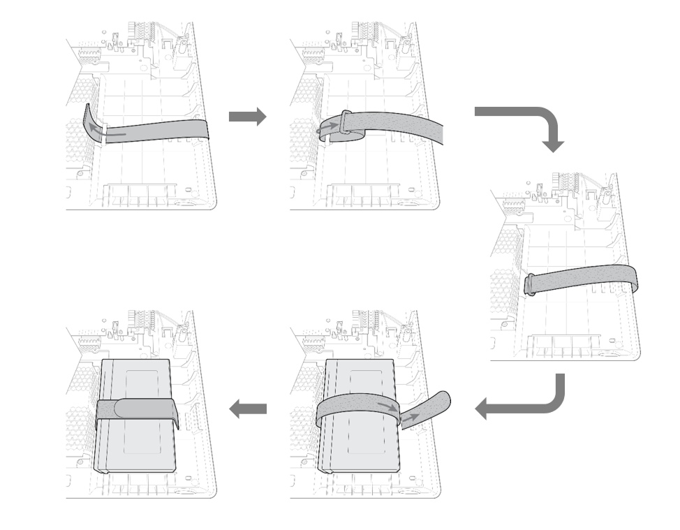
Backup battery fixing
Insert the battery Velcro strap into the case, then secure the battery.
Use a backup battery that is 12 VDC specification and 7 Ah or higher. This product has been tested with the 'ES7-12' product from 'ROCKET', and it is recommended to use products equivalent to 'ES7-12'.
-
The backup battery is sold separately.
-
Be sure to check the size and shape of the backup battery terminals. If the size of the backup battery exceeds the recommended specifications, it may not fit in the case or the case may not close after installation. Additionally, if the shape and size of the terminals are different, you will not be able to connect the battery using the provided cable.

Product Fixation
-
Check the location to mount the product in the enclosure. You can install 2 products in 1 enclosure.
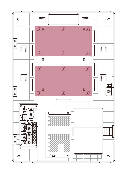
-
Place the product in the enclosure according to the mounting location and secure it with screws.
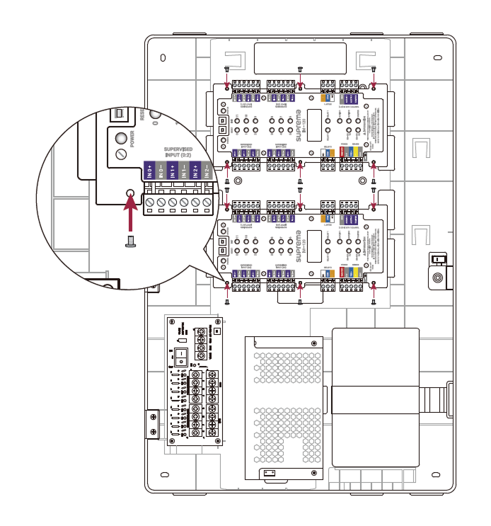
- The ENCR-10 is designed to be mounted on a wall for use. Install it at a safe and convenient height without restrictions on installation height.
-
The ENCR-10 components include screws for housing fixation, screws for product fixation, and screws for power device connection. Use each screw correctly according to its purpose.
-
Fixing screws for the enclosure (diameter: 4 mm, length: 25 mm) x4
-
Fixing screws for the device (diameter: 3 mm, length: 5 mm) x6
-
Fixing screws for the power supply cable (diameter: 3 mm, length: 8 mm) x1
-
Power and AUX input connection
To prevent power interruptions, you can connect an uninterruptible power supply (UPS), and contact outputs from power outage detectors or other devices can be connected to the AUX IN terminal.
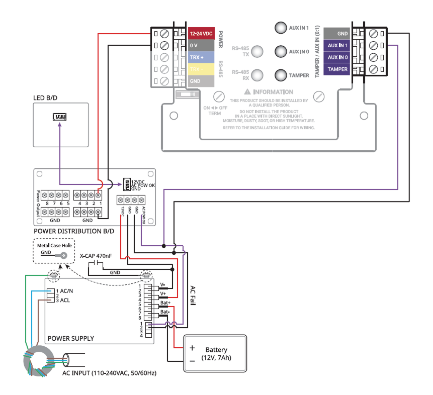
-
Make sure to use separate power for the access control device and products.
-
Use the IEC/EN 62368-1 approved power adapter that supports higher power consumption than the product. If you wish to connect and use another device to the power supply adapter, you should use an adapter with a current capacity which is the same or larger than the total power consumption required for the terminal and another device.
- Refer to the Power in the product specifications for maximum current consumption specifications.
-
DO NOT extend the length of power cable when using the power adapter.
-
Use a backup battery that is 12 VDC specification and 7 Ah or higher. This product has been tested with the 'ES7-12' product from 'ROCKET', and it is recommended to use products equivalent to 'ES7-12'.
Tamper Connection
If the enclosure is opened due to external factors, it can trigger an alarm or leave an event log.
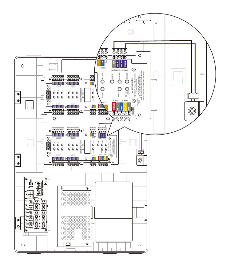
For more detailed information on product installation, contact Suprema Technical Support Team.