Last updated |
Getting Started
Overview of the ViOnyx camera's components, including the name and function of each part.
Components
Caution
The desiccant module comes in sealed packaging. Exposure to air can reduce dehumidification performance. Open the package just before attaching it.
|
|
|
|
| Cover | Camera Body | Mounting Plate | Drilling Template |
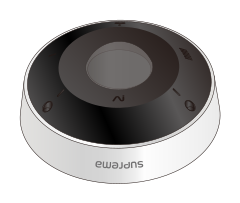
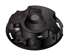
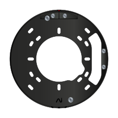
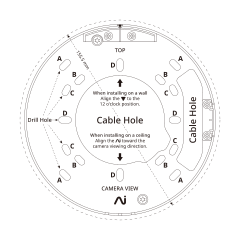
|
|
|
|
|
| Desiccant Module | Connection Cables | Waterproof Grommet for Ethernet Cable | Waterproof Rubber Hole Plug | Fixing Screw x4 |
|
|
|
|
|
| Diode | 120 Ω Resistor | T10 Torx Driver (Star-shaped) | Quick Guide | Open Source Software Guide |

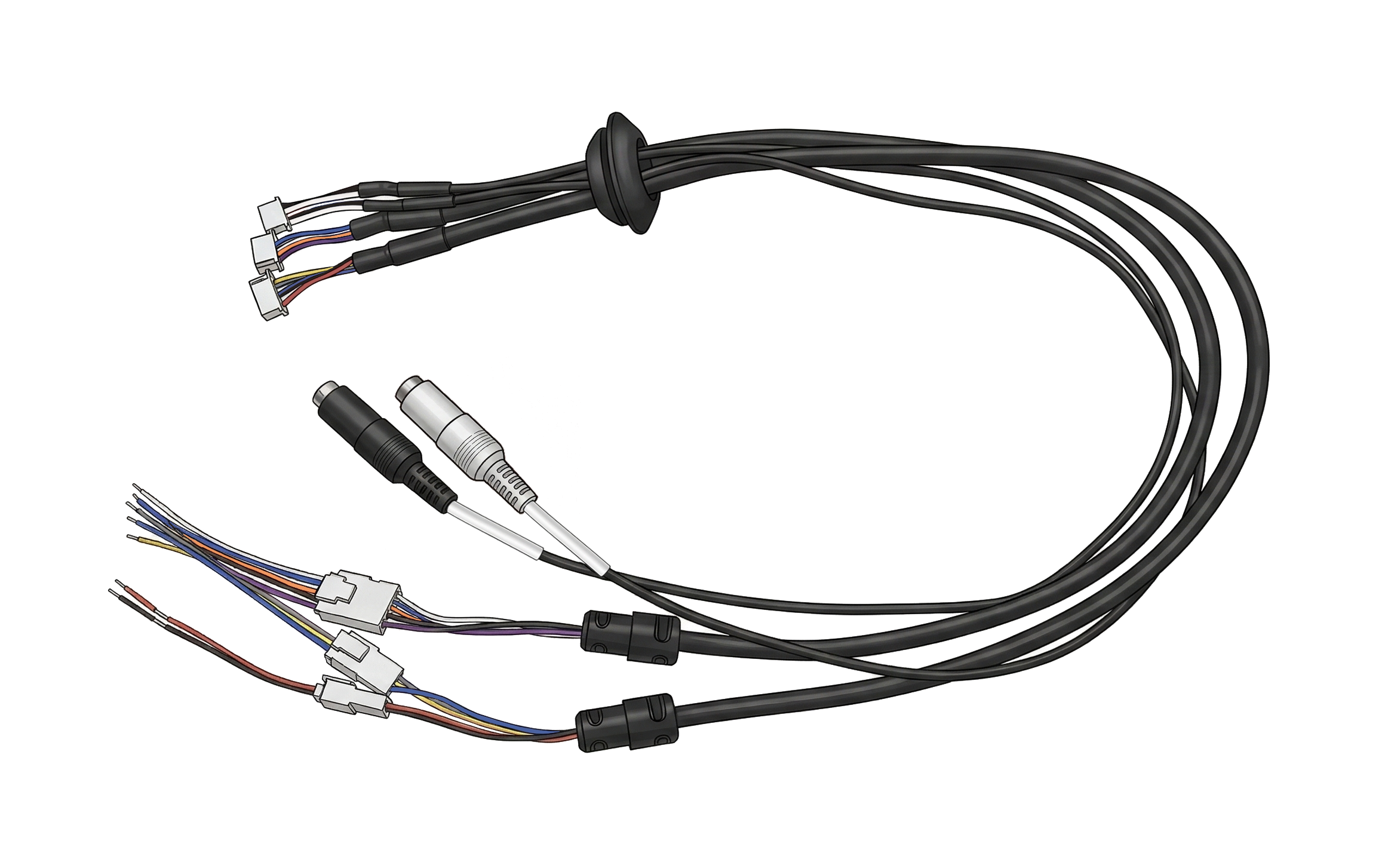
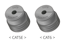

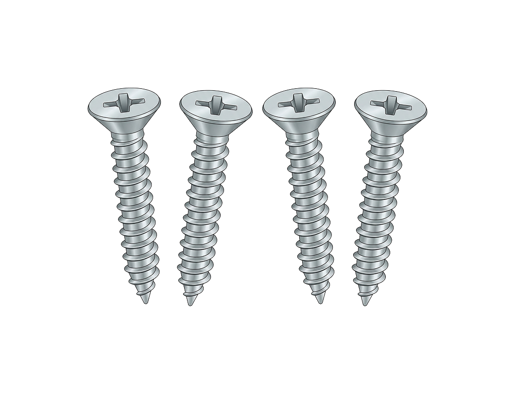
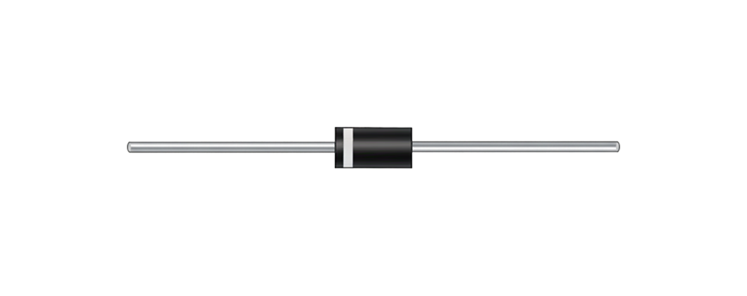
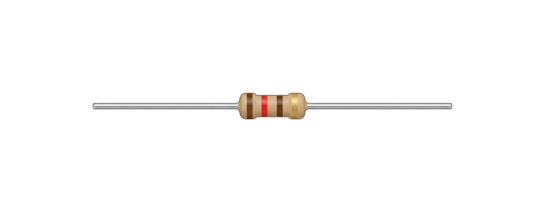
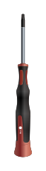
Info
- Components may vary according to the installation environment.
Name and function of each part
Internal port configuration
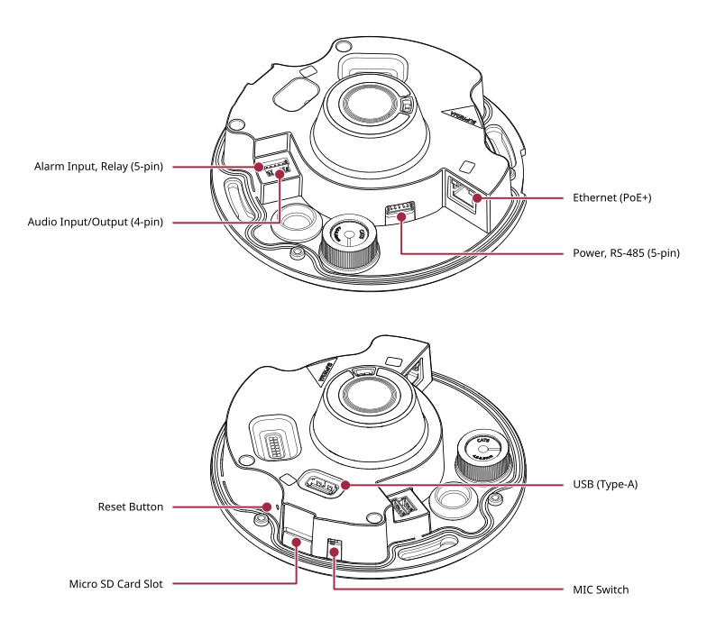
| Name | Function |
|---|---|
| Alarm Input, Relay (5-pin) | Connect the cable for alarm input and relay output. |
| Audio Input/Output (4-pin) | Connect the cable for audio input/output. |
| Ethernet (PoE+) | Connect the Ethernet cable. Power can be supplied via PoE+. |
| Power, RS-485 (5-pin) | Connect the cable for power and RS-485 communication. |
| Reset Button | Reset all settings to factory defaults. For more information on factory initialization, refer to Factory reset. |
| Micro SD Card Slot | Insert a microSD card. |
| USB (Type-A) | Connect USB-based accessories. |
| MIC Switch | Use the microphone switch to physically enable or disable audio recording. |
Cables and connectors
Power & RS-485

| Cable | Pin | Name | Color |
|---|---|---|---|
| POWER | 1 | PWR +VDC | Red |
| 2 | PWR GND | Black | |
| RS-485 | 3 | 485 TRXP | Blue |
| 4 | 485 TRXN | Yellow | |
| 5 | 485 GND | Gray |
Alarm input & relay

| Cable | Pin | Name | Color |
|---|---|---|---|
| ALARM_IN | 1 | ALARM IN | Purple |
| 2 | ALARM GND | Black | |
| RELAY | 3 | RLY NC | Orange |
| 4 | RLY COM | Blue | |
| 5 | RLY NO | White |
Audio input/output
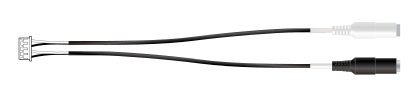
| Cable | Pin | Name | Color |
|---|---|---|---|
| LINE_IN | 1 | LINE IN | White |
| 2 | LINE IN GND | Black | |
| LINE_OUT | 3 | LINE OUT | White |
| 4 | LINE OUT GND | Black |
LED Status Indicator
The LED on the front of the camera cover shows the device's operating and authentication status using colors and blinking patterns.
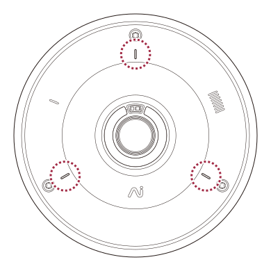
| LED color | Status |
|---|---|
| Green | Authentication successful |
| Red | Authentication failed |
| Blue | Normal operation |
| Blue/Green blinking | When setting DHCP to use, unable to retrieve IP address. |
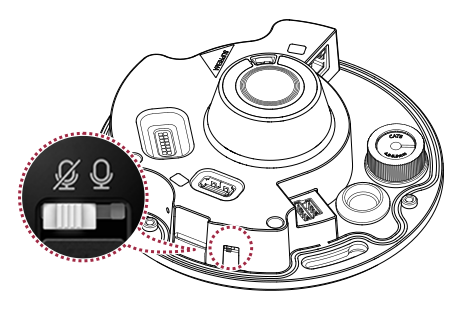
Microphone switch settings (coming soon)
Use the microphone switch to physically disable the camera's microphone and prevent audio recording.
-
Audio recording is disabled by default.
-
Slide the microphone switch to the right to enable audio recording.