Getting Started
Provides initial procedures for getting started with the device.
Components
|
|
|
|
| XPass 2 Mullion Type (XP2-MDPB, XP2-MAPB, XP2-MAPB-H) | Wall Bracket (XP2-MDPB, XP2-MAPB, XP2-MAPB-H) | XPass 2 Gang Box Type (XP2-GDPB) | Wall Bracket (XP2-GDPB) |
|
|
|
|
| XPass 2 Keypad Type (XP2-GKDPB) | Wall Bracket (XP2-GKDPB) | Fixing Screws x2 | Bracket Fixing Screw (Star Shaped) |


|
|
|
|
|
| Diode | 120 Ω Resistor | Shrink Tube | Quick Guide | Open Source Software Guide |


- Components may vary according to the installation environment.
- When assembling the product with the bracket, you can use the included bracket fixing screw (Star Shaped) instead of the product fixing screw for enhanced security.
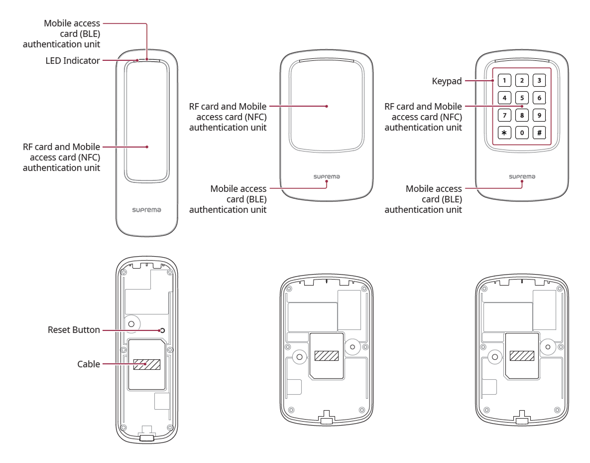
Name and function of each part
-
LED Indicator: Indicates the operational status of the device with the color of the LED.
-
Green: Authentication success.
-
Red: Authentication failure.
-
Blue/Cyan blinking: Normal operation.
-
Blue/Green blinking: During network settings initialization
-
Green blinking: Waiting for input.
-
Green/White blinking: Connecting to the Suprema AirFob Pass (BLE) application
-
White blinking: Connecting to the Device Manager application
-
-
RF card and mobile access card authentication unit: Part to scan a RFID card or mobile access card for entrance.
-
Mobile Access Card Recognition Area: This is the part that recognizes mobile access cards for entry.
-
Reset Button
-
Initializes network settings. For more information on initializing network settings, refer to Initialize Network Settings.
-
Deletes all information and certificates stored on the device and initializes the settings. For more information on factory initialization, refer to Factory default.
-
-
Cable
Power / RS-485 / Ethernet / Wiegand I/O / Input / Relay
-
Keypad: XP2-GKDPB Used to authenticate by directly entering the Card ID. To authenticate using direct input mode, change the authentication method settings in BioStar X.
-
0-9: Used when entering numbers.
-
 : Used to distinguish between FC code and ID when entering Wiegand Card ID.
 -
 : Used to terminate input.
-
Cable
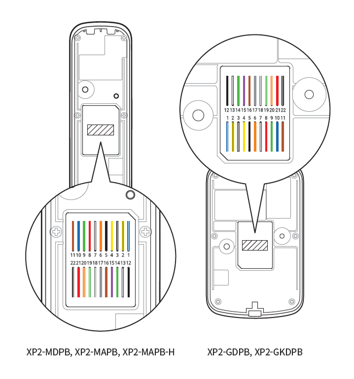
| Pin | Name | Color |
|---|---|---|
| 1 | 485 TRXP | Blue (White Stripe) |
| 2 | 485 TRXN | Yellow (Black Stripe) |
| 3 | 485 GND | White (Black Stripe) |
| 4 | ENET RXN | Yellow |
| 5 | ENET RXP | Black |
| 6 | ENET TXN | Orange |
| 7 | ENET TXP | White |
| 8 | ENET VB1 | Red |
| 9 | ENET VB1 | Green |
| 10 | ENET VB2 | Blue |
| 11 | ENET VB2 | Brown |
| 12 | WG GND | Black |
| 13 | WG D1 | White |
| 14 | WG D0 | Green |
| 15 | INPUT0 | Purple |
| 16 | INPUT1 | Brown |
| 17 | INPUT GND | Gray |
| 18 | RLY NO | Gray (White Stripe) |
| 19 | RLY COM | Green (White Stripe) |
| 20 | RLY NC | Orange (White Stripe) |
| 21 | PWR +VDC | Red |
| 22 | PWR GND | Black (White Stripe) |