Installation
Provides the complete installation procedures and connection examples required for the device.
Fixing the bracket and the product
This document explains the installation method based on the million type. Install the gang box type and keypad type in the same way.
-
Secure the bracket tightly using the fixing screws at the location where the product will be mounted.
 Info
Info-
If installing the product on a concrete wall, drill a hole, insert a PVC anchor, and secure it with a fixing screw.
-
To avoid RF interference, a minimum separation distance must be maintained.
XPD2-GDB, XPD2-GKDB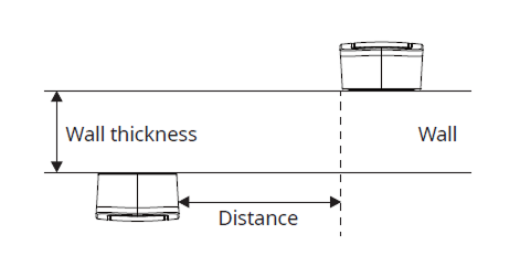
Wall thickness Distance 100 mm 360 mm 120 mm 360 mm 150 mm 300 mm 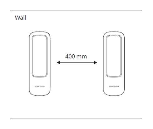
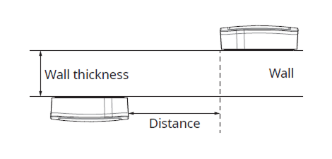
Wall thickness Distance 100 mm 400 mm 120 mm 380 mm 150 mm 380 mm 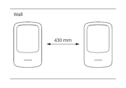
- When using a mobile access card, install devices maintaining a minimum distance of 1 m between devices to avoid BLE interference.
-
-
Mount the product on the fixed bracket.

-
Rotate the fixing screws to assemble the product with the bracket.
 Info
InfoWhen assembling the product with the bracket, you can use the included bracket fixing screw (Star Shaped) instead of the product fixing screw for enhanced security.
Power supply connection
This product can be used as an RFID card or mobile card reader by connecting to a master device or CoreStation.
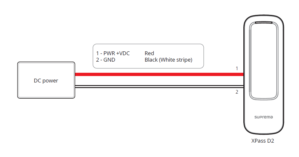
-
Use the IEC/EN 62368-1 approved power adapter that supports higher power consumption than the product. If you wish to connect and use another device to the power supply adapter, you should use an adapter with a current capacity which is the same or larger than the total power consumption required for the terminal and another device.
- Refer to the Power in the product specifications for maximum current consumption specifications.
-
DO NOT extend the length of power cable when using the power adapter.
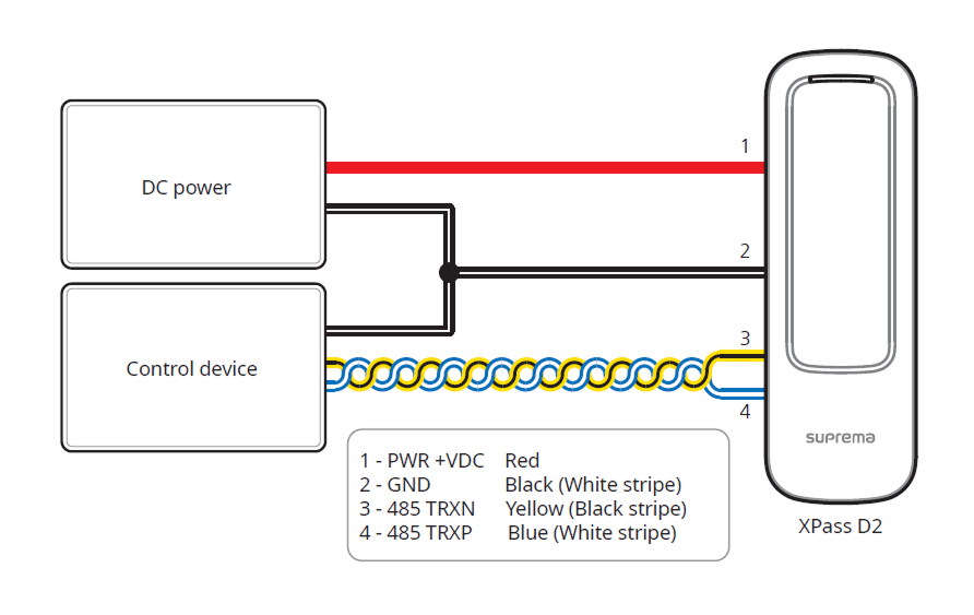
RS-485 Connection
-
Use an AWG24 twisted pair with a maximum length of 1.2 km for the RS-485 cable.
-
It is recommended to use RS-485 cables with a characteristic impedance of 120 Ω.
-
If connecting with a RS-485 daisy chain, connect the termination resistor (120 Ω) to both ends of the daisy chain connection. If connected to the middle line, the signal level becomes smaller and the communication performance will deteriorate. Make sure to connect it to both ends of the daisy chain connection.
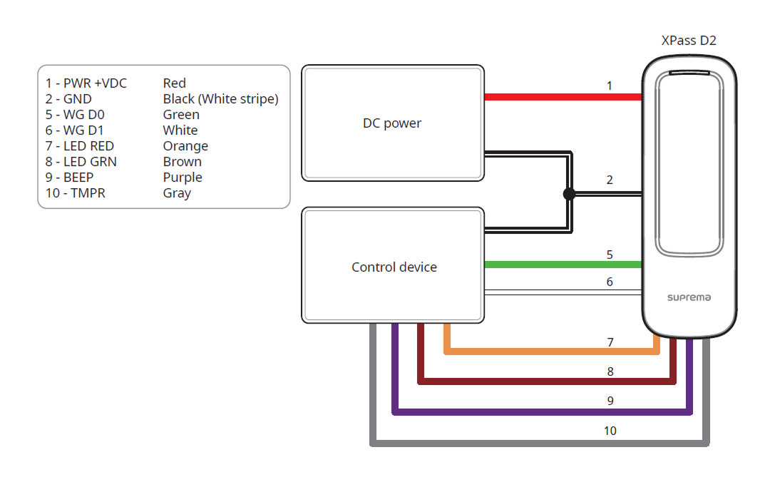
Wiegand and other cable connections
Factory default
Delete all information stored on the device and initialize the settings.
-
Power on.
-
Quickly press the reset button three times.

-
Press the reset button once more when the device's LED blinks green.
You can only use Factory Default when the root certificate is stored on the device.
Reset RS-485 transmission performance
You can choose and set the desired communication performance.
-
Power on.
-
Press the reset button for more than 2 seconds. When you enter setting mode, the LED flashes green.
-
When the device's LED flashes green, press the reset button as many times as desired. The transmission performance is set according to the number of presses, and you can check the set performance by the LED color.
Number of presses Transmission performance LED color 1 9600 Sky blue 2 19200 Blue 3 38400 Purple 4 57600 White 5 115200 Red -
The LED color of the set transmission performance flashes for 5 seconds. When you hear a beep, the transmission performance setting is complete.
If you do not press the reset button after entering setting mode, the transmission performance will automatically be set to 115200.