Installation
Provides the complete installation procedures and connection examples required for the device.
Fixing the bracket and the product
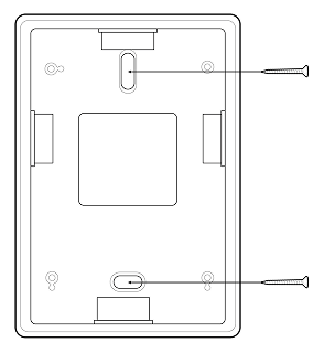
General bracket
-
Secure the bracket tightly using the fixing screws at the location where the product will be mounted.
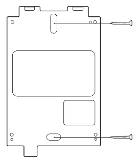 Info
InfoIf installing the product on a concrete wall, drill a hole, insert a PVC anchor, and secure it with a fixing screw.
-
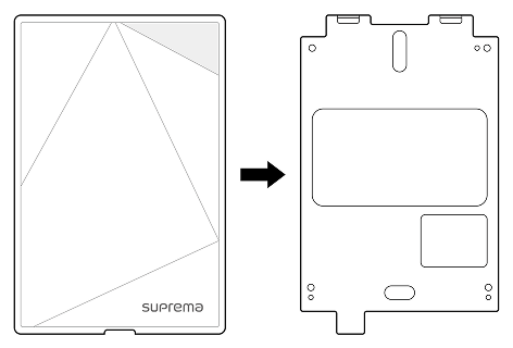
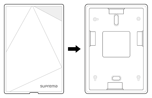
Mount the product on the fixed bracket.
-
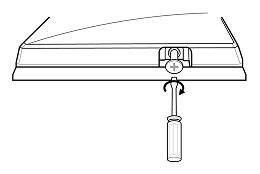
Rotate the fixing screws to assemble the product with the bracket.
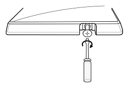 Info
InfoWhen assembling the product with the bracket, you can use the included bracket fixing screw (Star Shaped) instead of the product fixing screw for enhanced security.
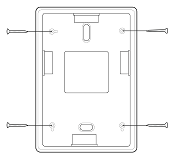
Extension Bracket
-
Assemble the standard bracket and extension bracket using the fixed screws included with the extension bracket.
-
Secure the extension bracket firmly in position using the fixed screws.
 Info
InfoIf installing the product on a concrete wall, drill a hole, insert a PVC anchor, and secure it with a fixing screw.
-
Mount the product on the secured extension bracket.
-
Screw the product screws to assemble the product and extension bracket.
 Info
InfoWhen assembling the extension bracket and product, you can use the included bracket fixing screws (star-shaped) instead of the product screws for enhanced security.
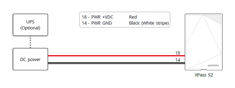
Power supply connection
-
Use the IEC/EN 62368-1 approved power adapter that supports higher power consumption than the product. If you wish to connect and use another device to the power supply adapter, you should use an adapter with a current capacity which is the same or larger than the total power consumption required for the terminal and another device.
- Refer to the Power in the product specifications for maximum current consumption specifications.
- Use a separate power supply for Secure I/O 2, the electric lock, and the product respectively. If connecting and using the power supply to these devices together, the devices may malfunction.
- DO NOT extend the length of power cable when using the power adapter.
Network Connection
TCP/IP
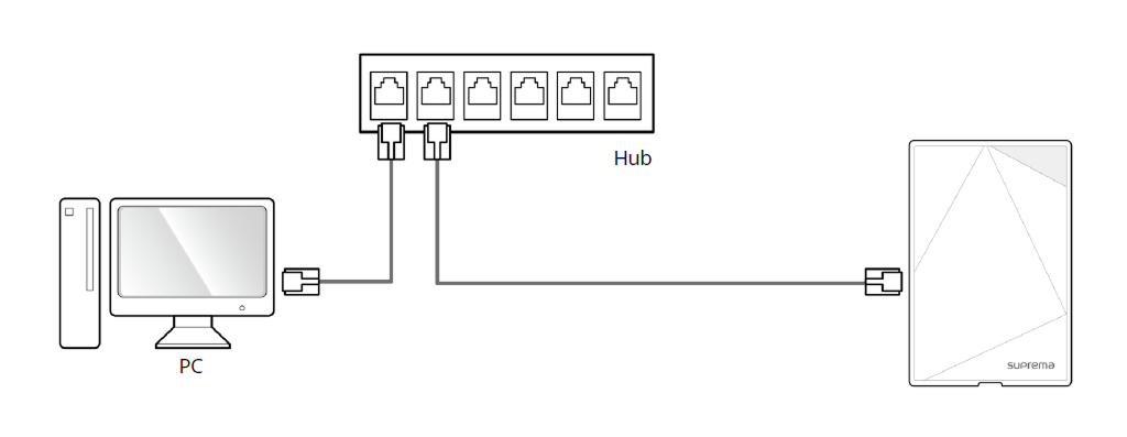
LAN connection (connecting to a hub)
You can connect to a hub using a standard CAT-5 or higher cable.
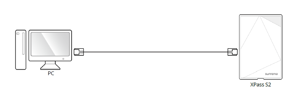
LAN connection (connecting to a PC directly)
This product supports automatic MDI/MDIX, so it can connect directly to a PC using a standard CAT-5 or higher cable.
Network ports and services
This device uses the following ports for network communication and stable service operation.
| Protocol | Service |
|---|---|
| TCP | Used for communication services between the server and the device, and for the device operation status switching service. |
| UDP | Used for the device discovery service to search for devices on the network. |
These ports are used to provide normal network features of the product. When configuring firewall rules or network security settings, allow the use of these ports.
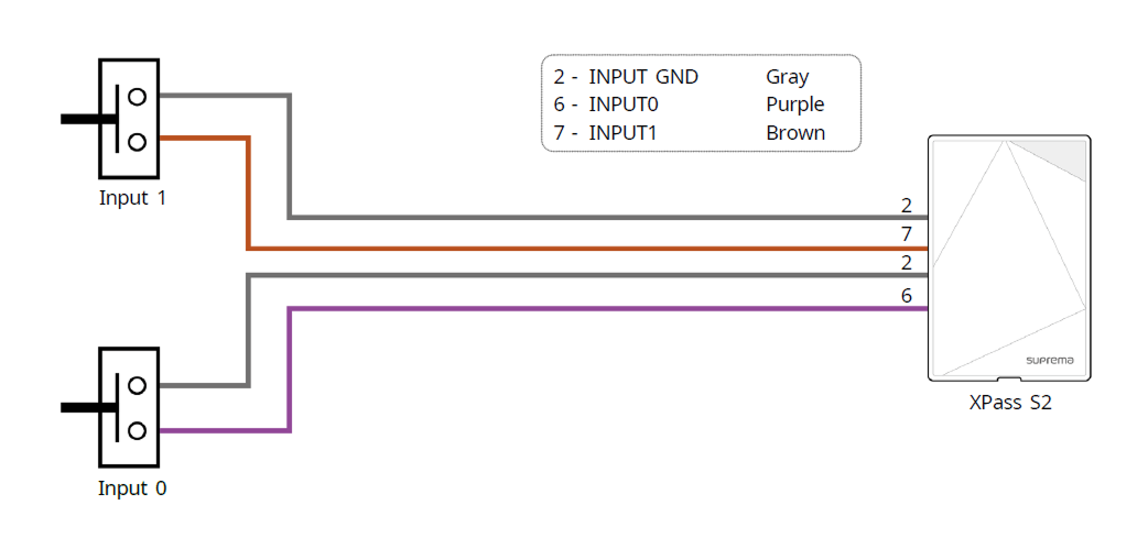
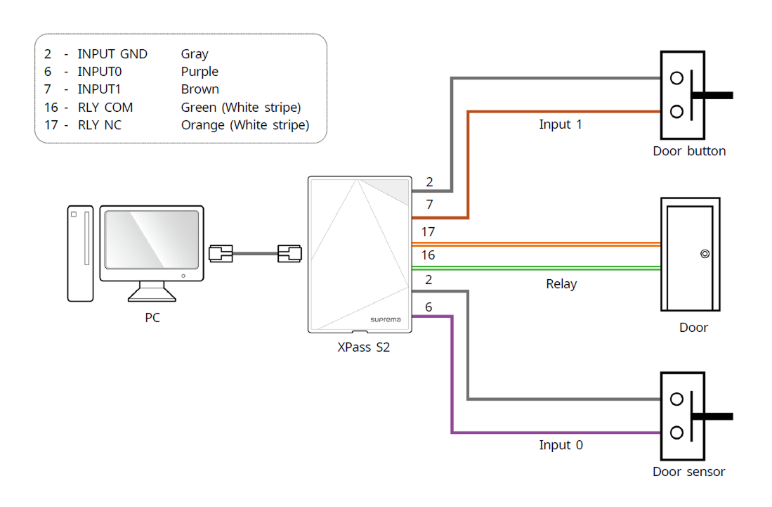
Door sensor and exit button
Exit button, door sensor

Alarm, emergency switch
Relay Connection
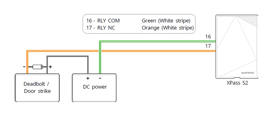
Fail Safe Lock
In order to use the Fail Safe Lock, connect N/C relay as shown in the figure below. There is normally a current flowing through the relay for the Fail Safe Lock. When the relay is activated, blocking the current flow, the door will open. If the power supply to the product is cut off due to a power failure or an external factor, the door will open.
-
Install a diode at both sides of the door lock wire as shown in the figure to protect the relay from the reverse current, which occurs when the door lock operates.
-
Use a separate power supply for the product and the door lock.
-
Suprema’s standalone intelligent readers contain internal relays that can directly lock/unlock doors without external controllers for added convenience. For access control applications in need of security, however, it is NOT recommended to use the internal relay of a reader to prevent any tampering attacks which can potentially trigger the door unlock. For such applications, it is highly recommended to use a separate relay unit for a lock control such as Suprema’s Secure I/O 2, DM-20 or CoreStation installed at a secure side of a door.
Take caution of the installation direction of the diode. Install the diode close to the door lock.
Fail Secure Lock
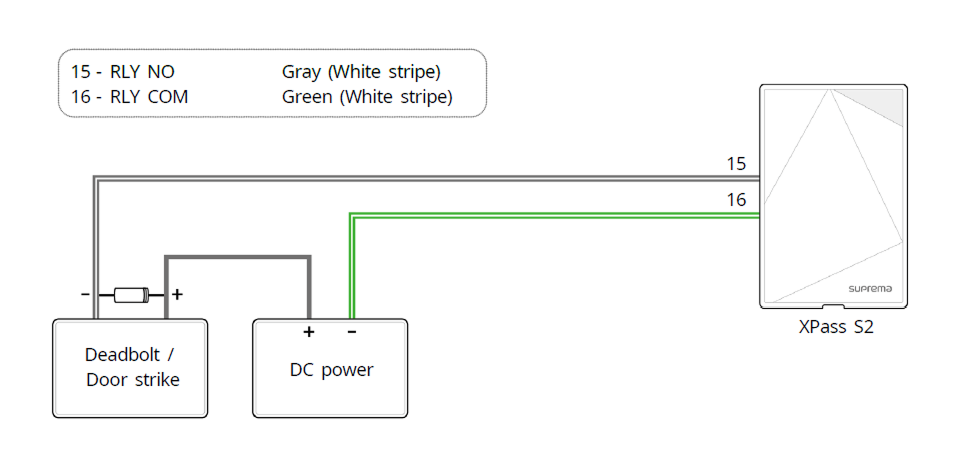
In order to use the Fail Secure Lock, connect N/O relay as shown in the figure below. There is normally no current flowing through the relay for the Fail Secure Lock. When the current flow is activated by the relay, the door will open. If the power supply to the product is cut off due to a power failure or an external factor, the door will lock.
-
Install a diode at both sides of the door lock wire as shown in the figure to protect the relay from the reverse current, which occurs when the door lock operates.
-
Use a separate power supply for the product and the door lock.
-
Suprema’s standalone intelligent readers contain internal relays that can directly lock/unlock doors without external controllers for added convenience. For access control applications in need of security, however, it is NOT recommended to use the internal relay of a reader to prevent any tampering attacks which can potentially trigger the door unlock. For such applications, it is highly recommended to use a separate relay unit for a lock control such as Suprema’s Secure I/O 2, DM-20 or CoreStation installed at a secure side of a door.
Take caution of the installation direction of the diode. Install the diode close to the door lock.
Automatic door connection
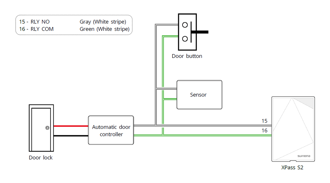
Connecting as a Standalone
The product can be connected to the door lock, door button, and door sensor directly without connecting a separate I/O device.
Suprema’s standalone intelligent readers contain internal relays that can directly lock/unlock doors without external controllers for added convenience. For access control applications in need of security, however, it is NOT recommended to use the internal relay of a reader to prevent any tampering attacks which can potentially trigger the door unlock. For such applications, it is highly recommended to use a separate relay unit for a lock control such as Suprema’s Secure I/O 2, DM-20 or CoreStation installed at a secure side of a door.
- Connect up to 31 slave devices to a master device.
- For more information, contact the Suprema Technical Support Team.
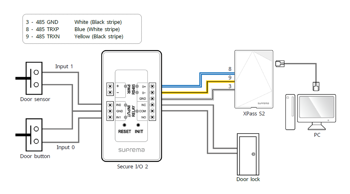
Connecting to Secure I/O 2
Secure I/O 2 is an I/O device, can be connected to the product with the RS-485 cable. Security can be maintained even if the connection between the product and Secure I/O 2 has been lost or the power supply to the product has been shut off due to external factors.
-
Use an AWG24 twisted pair with a maximum length of 1.2 km for the RS-485 cable.
-
It is recommended to use RS-485 cables with a characteristic impedance of 120 Ω.
-
If connecting with a RS-485 daisy chain, connect the termination resistor (120 Ω) to both ends of the daisy chain connection. If connected to the middle line, the signal level becomes smaller and the communication performance will deteriorate. Make sure to connect it to both ends of the daisy chain connection.
- Connect up to 31 slave devices to a master device.
- For more information, contact the Suprema Technical Support Team.
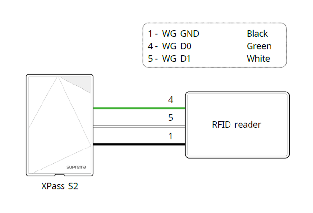
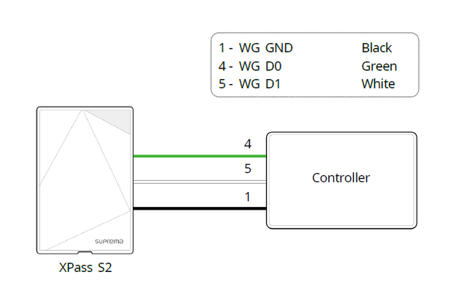
Wiegand Connection
Used as a Wiegand input device.
Used as a Wiegand output device.
Initialize Network Settings
Initialize the device's network settings.
-
Power on.
-
Press the reset button until the device automatically reboots.
-
Connect the device using the initialized network information.
-
TCP/IP Address: DHCP address assignment (if DHCP address assignment fails, will be set to 169.254.x.x).
-
Server Mode: Disable
-
RS-485: Default, 115200 bps
-
-
Change the TCP/IP or RS-485 information.
-
Check if the network information is correctly set after turning the power off and on.
Factory default
Delete all information stored on the device and initialize the settings.
-
Power on.
-
Quickly press the reset button three times.

-
Press the reset button once more when the device's LED blinks Yellow.
You can only use Factory Default when the root certificate is stored on the device.