Installation
Provides the complete installation procedures and connection examples required for the device.
Fixing the bracket and the product
This document explains the installation method based on the XS2-ODPB and XS2-OAPB form factor. Install the XS2-DPB, XS2-APB, XS2-QDPB, and XS2-QAPB models in the same way.
-
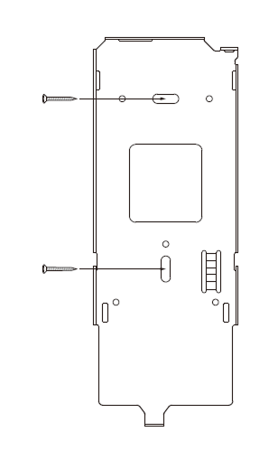
Determine the correct position to install the bracket using the provided drilling template. Secure the bracket tightly using the fixing screws at the location where the product will be mounted.
 Info
Info-
If installing the product on a concrete wall, drill a hole, insert a PVC anchor, and secure it with a fixing screw.
-
To avoid RF interference, a minimum separation distance must be maintained.
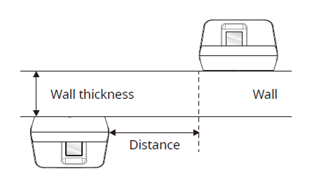
Wall thickness Distance 100 mm 500 mm 120 mm 400 mm 150 mm 300 mm 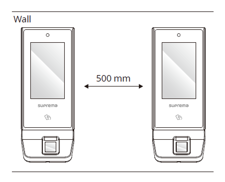
- When using a mobile access card, install devices maintaining a minimum distance of 1 m between devices to avoid BLE interference.
-
-
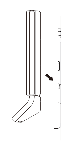
After attaching the cable cover, turn the four screws fitted in the cover to fasten it securely and mount the product on the fixed bracket.
 Info
InfoMake sure that the cable cover is completely closed after connecting it to the product to maintain the water-resistant and dust-resistant features (IP65 rating).
-
Rotate the fixing screws to assemble the product with the bracket.
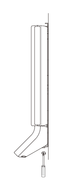 Info
InfoWhen assembling the product with the bracket, you can use the included bracket fixing screw (Star Shaped) instead of the product fixing screw for enhanced security.
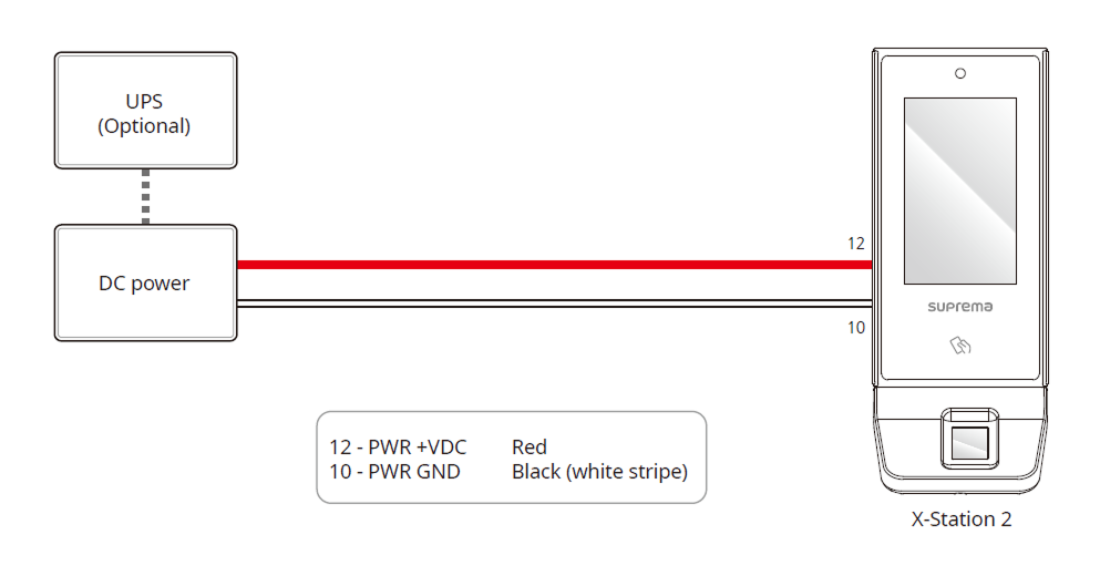
Power supply connection
- DO NOT connect the device to the DC power supply (or adapter) and PoE power supply at the same time.
-
Use the IEC/EN 62368-1 approved power adapter that supports higher power consumption than the product. If you wish to connect and use another device to the power supply adapter, you should use an adapter with a current capacity which is the same or larger than the total power consumption required for the terminal and another device.
- Refer to the Power in the product specifications for maximum current consumption specifications.
- Use a separate power supply for Secure I/O 2, the electric lock, and the product respectively. If connecting and using the power supply to these devices together, the devices may malfunction.
- DO NOT extend the length of power cable when using the power adapter.
- DO NOT use the CAT5 UTP 2-Wire for power supply purpose.
Network Connection
TCP/IP
LAN connection (connecting to a hub)
You can connect to a hub using a standard CAT-5 or higher cable.
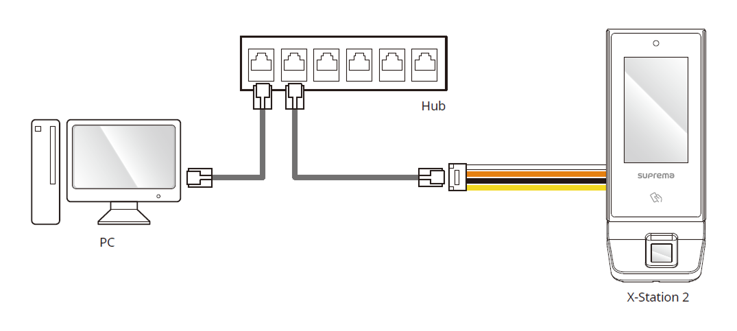
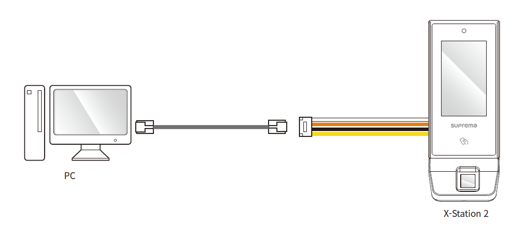
LAN connection (connecting to a PC directly)
This product supports automatic MDI/MDIX, so it can connect directly to a PC using either a crossover cable or a standard straight CAT-5 or higher cable.
Network ports and services
This device uses the following ports for network communication and stable service operation.
| Protocol | Service |
|---|---|
| TCP | Used for communication services between the server and the device, and for the device operation status switching service. |
| UDP | Used for the device discovery service to search for devices on the network. |
These ports are used to provide normal network features of the product. When configuring firewall rules or network security settings, allow the use of these ports.
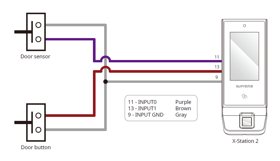
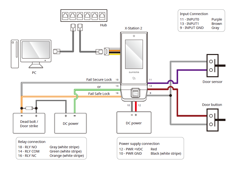
Input connection
Relay Connection
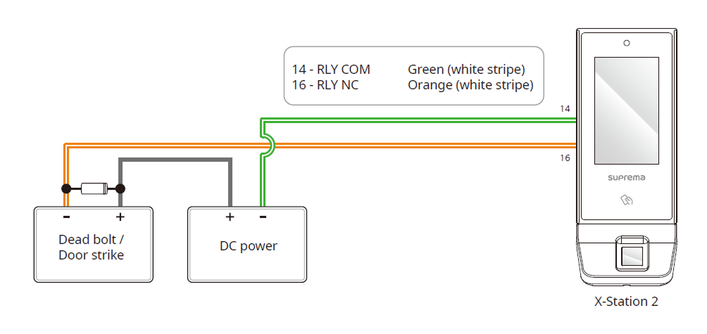
Fail Safe Lock
In order to use the Fail Safe Lock, connect N/C relay as shown in the figure below. There is normally a current flowing through the relay for the Fail Safe Lock. When the relay is activated, blocking the current flow, the door will open. If the power supply to the product is cut off due to a power failure or an external factor, the door will open.
-
Install a diode at both sides of the door lock wire as shown in the figure to protect the relay from the reverse current, which occurs when the door lock operates.
-
Use a separate power supply for the product and the door lock.
-
Suprema’s standalone intelligent readers contain internal relays that can directly lock/unlock doors without external controllers for added convenience. For access control applications in need of security, however, it is NOT recommended to use the internal relay of a reader to prevent any tampering attacks which can potentially trigger the door unlock. For such applications, it is highly recommended to use a separate relay unit for a lock control such as Suprema’s Secure I/O 2, DM-20 or CoreStation installed at a secure side of a door.
Take caution of the installation direction of the diode. Install the diode close to the door lock.
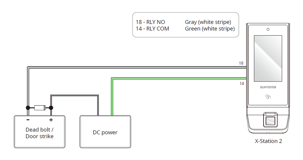
Fail Secure Lock
In order to use the Fail Secure Lock, connect N/O relay as shown in the figure below. There is normally no current flowing through the relay for the Fail Secure Lock. When the current flow is activated by the relay, the door will open. If the power supply to the product is cut off due to a power failure or an external factor, the door will lock.
-
Install a diode at both sides of the door lock wire as shown in the figure to protect the relay from the reverse current, which occurs when the door lock operates.
-
Use a separate power supply for the product and the door lock.
-
Suprema’s standalone intelligent readers contain internal relays that can directly lock/unlock doors without external controllers for added convenience. For access control applications in need of security, however, it is NOT recommended to use the internal relay of a reader to prevent any tampering attacks which can potentially trigger the door unlock. For such applications, it is highly recommended to use a separate relay unit for a lock control such as Suprema’s Secure I/O 2, DM-20 or CoreStation installed at a secure side of a door.
Take caution of the installation direction of the diode. Install the diode close to the door lock.
Automatic door connection
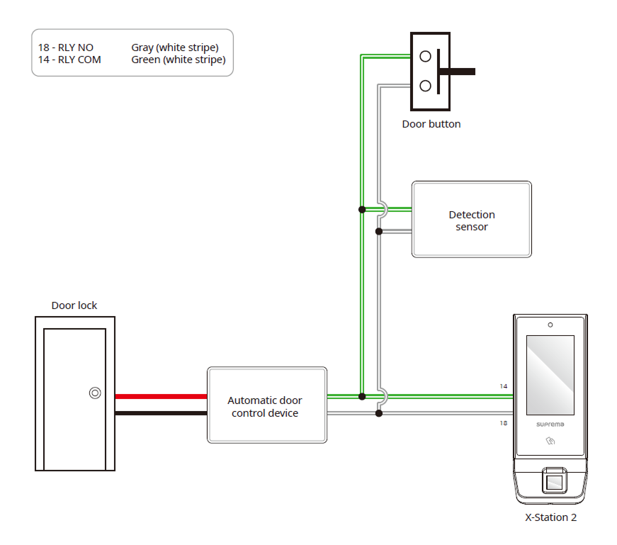
Connecting as a Standalone
The product can be connected to the door lock, door button, and door sensor directly without connecting a separate I/O device.
Suprema’s standalone intelligent readers contain internal relays that can directly lock/unlock doors without external controllers for added convenience. For access control applications in need of security, however, it is NOT recommended to use the internal relay of a reader to prevent any tampering attacks which can potentially trigger the door unlock. For such applications, it is highly recommended to use a separate relay unit for a lock control such as Suprema’s Secure I/O 2, DM-20 or CoreStation installed at a secure side of a door.
- The device can be used as a multi-door controller with the slave devices with the RS-485 cable. The slave devices are used as dummy readers and authentication is performed in the master device.
-
The maximum number of slave devices available to connect varies according to the authentication method, number of users, and number of devices. Also note that the number of slave devices affects the authentication performance.
-
Connect up to 31 slave devices to a master device. The bandwidth of RS-485 allows for up to 7 fingerprint authentication devices to be connected.
- For more information, contact the Suprema Technical Support Team.
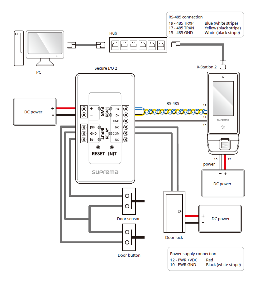
Connecting to Secure I/O 2
Secure I/O 2 is an I/O device, can be connected to the product with the RS-485 cable. Security can be maintained even if the connection between the product and Secure I/O 2 has been lost or the power supply to the product has been shut off due to external factors.
-
Use an AWG24 twisted pair with a maximum length of 1.2 km for the RS-485 cable.
-
It is recommended to use RS-485 cables with a characteristic impedance of 120 Ω.
-
If connecting with a RS-485 daisy chain, connect the termination resistor (120 Ω) to both ends of the daisy chain connection. If connected to the middle line, the signal level becomes smaller and the communication performance will deteriorate. Make sure to connect it to both ends of the daisy chain connection.
- The device can be used as a multi-door controller with the slave devices with the RS-485 cable. The slave devices are used as dummy readers and authentication is performed in the master device.
-
The maximum number of slave devices available to connect varies according to the authentication method, number of users, and number of devices. Also note that the number of slave devices affects the authentication performance.
-
Connect up to 31 slave devices to a master device. The bandwidth of RS-485 allows for up to 7 fingerprint authentication devices to be connected.
- For more information, contact the Suprema Technical Support Team.
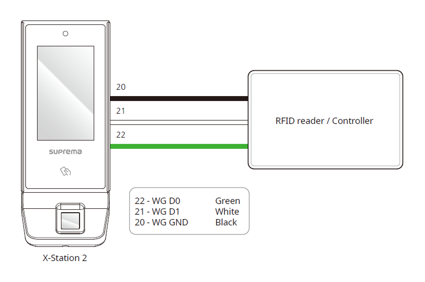
Wiegand Connection
Use as a Wiegand input or output device.